Toyota Sienna Service Manual: Lock Switch Circuit
DESCRIPTION
Each of the left and right seats has lock switches that detect the lock condition of the seat legs to the floor when the seat is in the original or folded-down state. If any of the lock switches detect an unlock condition, the 3rd SEAT indicator on the combination meter will come on and the folding-down, return, and reclining operations will be disabled.
WIRING DIAGRAM

INSPECTION PROCEDURE
1 INSPECT FOLD SEAT CONTROL ECU
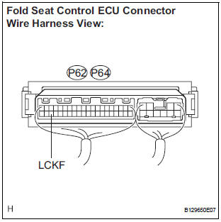
- Remove the fold seat control ECU with connector still connected.
- Measure the voltage according to the value(s) in the table below.
Standard voltage LH side

RH side

2 CHECK HARNESS AND CONNECTOR (FOLD SEAT CONTROL ECU - LOCK SWITCH)

- Disconnect the connectors from the fold seat control ECU.
- Disconnect the connector from the lock switch.
- Measure the resistance according to the value(s) in the table below.
Standard resistance LH side

RH side

3 CHECK HARNESS AND CONNECTOR (LOCK SWITCH - BODY GROUND)

- Measure the resistance according to the value(s) in the table below.
Standard resistance LH side

RH side

4 REPLACE LOCK SWITCH
HINT: Since the lock switch cannot be inspected while it is removed from the vehicle, replace the lock switch with a normal one and check that the condition returns to normal.
OK: Same problem does not occur.
REPLACE FOLD SEAT CONTROL ECU
 Release Actuator Circuit
DESCRIPTION
The fold seat control ECU receives a switch operation signal from the fold
seat switch and activates the
release actuator. The release actuator releases the lock of the stowed seat
b ...
 Rear Power Seat Switch Circuit
DESCRIPTION
When the power rear no. 2 seat switch is operated, a recline signal is sent
to the fold seat control ECU.
The ECU activates the reclining motor based on the signal from the power rea ...
Other materials:
Readiness monitor drive
pattern
1. PURPOSE OF READINESS TESTS
The On-Board Diagnostic (OBD II) system is
designed to monitor the performance of emissionrelated
components, and indicate any detected
abnormalities with DTCs (Diagnostic Trouble Codes).
Since various components need to be monitored in
different d ...
Removal
1. DRAIN POWER STEERING FLUID
2. REMOVE FRONT WHEEL RH
3. REMOVE FRONT FENDER APRON SEAL RH (See
page EM-26)
4. REMOVE FAN AND GENERATOR V BELT (See page
EM-6)
5. DISCONNECT NO. 1 FLUID RESERVOIR TO PUMP HOSE
(a) Slide the clip and disconnect the No. 1 fluid
reservoir to pump hose from t ...
Power Window can be Operated After Ignition Switch is Turned OFF
Even if Operative Conditions are not Met
DESCRIPTION
The multiplex network body ECU controls power supplied to the power window
master switch and each
regulator switch continuously for 45 seconds after the ignition switch is turned
OFF unless the front doors
have been opened, so that the power window can be operated during this peri ...
