Toyota Sienna Service Manual: Removal
1. DRAIN POWER STEERING FLUID
2. REMOVE FRONT WHEEL RH
3. REMOVE FRONT FENDER APRON SEAL RH (See page EM-26)
4. REMOVE FAN AND GENERATOR V BELT (See page EM-6)
5. DISCONNECT NO. 1 FLUID RESERVOIR TO PUMP HOSE

(a) Slide the clip and disconnect the No. 1 fluid reservoir to pump hose from the vane pump assembly.
6. DISCONNECT PRESSURE FEED TUBE ASSEMBLY
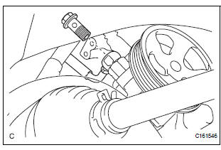
(a) Remove the union bolt and disconnect the pressure feed tube assembly from the vane pump assembly.
(b) Remove the gasket from the pressure feed tube assembly.
7. DISCONNECT POWER STEERING FLUID PRESSURE SWITCH CONNECTOR

(a) Disconnect the power steering fluid pressure switch connector.
8. REMOVE VANE PUMP ASSEMBLY
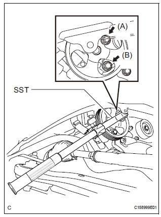
(a) Using SST, loosen bolt (A) and remove bolt (B), and then remove the vane pump assembly.
SST 09249-63010
(b) Remove the bolt from the vane pump assembly.
 Vane pump
COMPONENTS
...
 Disassembly
1. HOLD VANE PUMP ASSEMBLY
(a) Using SST, hold the vane pump assembly in a vise.
SST 09630-00014 (09631-00132)
2. REMOVE POWER STEERING SUCTION PORT UNION
(a) Remove the bolt and the pow ...
Other materials:
Engine Immobiliser System Malfunction
DTC B2799 Engine Immobiliser System Malfunction
DESCRIPTION
This DTC is output when the ECM detects errors in communication between the
transponder key ECU
and the ECM, or in the communication lines. This DTC is also output when an
engine start is attempted
while the ECU communication ID bet ...
ACIS Control Circuit
DESCRIPTION
This circuit opens and closes the Intake Air Control Valve (IACV) in response
to changes in the engine
load in order to increase the intake efficiency (ACIS: Acoustic Control
Induction System).
When the engine speed is between 0 and 4450 rpm and the throttle valve opening
angl ...
Throttle / Pedal Position Sensor/ Switch
DTC P2120 Throttle / Pedal Position Sensor / Switch "D"
Circuit
DTC P2122 Throttle / Pedal Position Sensor / Switch "D"
Circuit Low Input
DTC P2123 Throttle / Pedal Position Sensor / Switch "D"
Circuit High Input
DTC P2125 Throttle / Pedal Position Sensor / Switch ...
