Toyota Sienna Service Manual: Rear Air Outlet Damper Position Sensor Circuit
DESCRIPTION

This sensor detects the position of the rear air outlet control servo motor and sends the appropriate signals to the A/C amplifier. The position sensor is built in the rear air outlet control servo motor.
The position sensor's resistance changes as the rear air outlet control servo motor arm moves.
It outputs voltage (5 V) that is input to terminal 2 and terminal 3 via the variable resister, and then to the A/ C amplifier.
The A/C amplifier determines the arm position based on the input voltage from
the position sensor.
WIRING DIAGRAM

INSPECTION PROCEDURE
1 READ VALUE OF INTELLIGENT TESTER
(a) Connect the intelligent tester to the DLC3.
(b) Turn the ignition switch to the ON position and turn the intelligent tester main switch on.
(c) Select the items below in the DATA LIST, and read the display on the intelligent tester.
DATA LIST / AIR CONDITIONER 
OK: The display is as specified in the normal condition column.
Result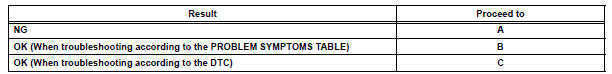


2 INSPECT REAR AIR OUTLET CONTROL SERVO MOTOR

(a) Remove the rear air outlet control servo motor.
(b) Disconnect the connector from the rear air outlet control servo motor.
(c) Measure the resistance according to the value(s) in the table below.
Standard resistance
(d) Measure the resistance according to the value(s) in the table below.
Standard resistance 

(e) As the rear air outlet control servo motor moves from FACE to FOOT, the resistance decreases gradually without interruption.


3 CHECK HARNESS AND CONNECTOR (REAR AIR OUTLET CONTROL SERVO MOTOR - A/C AMPLIFIER)

(a) Disconnect the connector from the A/C amplifier.

(b) Measure the resistance according to the value(s) in the table below.
Standard resistance 


REPLACE A/C AMPLIFIER
 Rear Air Mix Damper Position Sensor Circuit
DESCRIPTION
This sensor detects the position of the rear air mix control servo motor
(water valve servo motor) and
sends the appropriate signals to the A/C amplifier. The position sensor is bu ...
 Air Mix Damper Control Servo Motor Circuit (Passenger Side)
DESCRIPTION
The air mix control servo motor (air mix damper servo sub-assembly) is
controlled by the A/C amplifier.
The air mix control servo motor moves the air mix damper by rotating (normal, ...
Other materials:
Inner rear view mirror
COMPONENTS
REMOVAL
1. REMOVE INNER REAR VIEW MIRROR ASSEMBLY
w/ EC mirror:
Remove the inner rear view mirror cover.
w/ EC mirror:
Disconnect the connector.
Remove the screw.
Remove the inner rear view mirror assembly as
shown in the illustration.
IN ...
How to scroll
: Select to scroll to the next
or previous page.
: If
appears to the right of
titles, the complete titles are
too long for the display. Select
this button to scroll the title.
Turn the “TUNE•SCROLL” knob
to move the cursor box to select a
desired item from the list, and
press ...
Noise Occurs from Generator while Engine is Running
INSPECTION PROCEDURE
1 CHECK LOOSENESS OF V-RIBBED BELT
(a) Check the tension of the belt by pushing it down with a
finger.
OK:
The tension of the belt is enough.
2 CHECK V-RIBBED BELT FOR WEAR
(a) Check the V-ribbed belt for wear.
OK:
The V-ribbed belt is not worn.
3 CHECK CLUTC ...
