Toyota Sienna Service Manual: Rear Air Mix Damper Position Sensor Circuit
DESCRIPTION

This sensor detects the position of the rear air mix control servo motor (water valve servo motor) and sends the appropriate signals to the A/C amplifier. The position sensor is built in the rear air mix control servo motor (water valve servo motor).
The position sensor's resistance changes as the rear air mix control servo motor valve moves.
It outputs voltage (5 V) that is input to terminal 2 and terminal 3 via the variable resistor, and then to the A/ C amplifier.
The A/C amplifier determines the valve position based on the input voltage from
the position sensor.
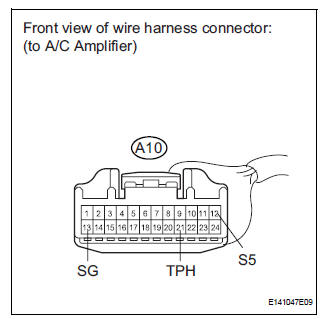
WIRING DIAGRAM

INSPECTION PROCEDURE
1 READ VALUE OF INTELLIGENT TESTER
(a) Connect the intelligent tester to the DLC3.
(b) Turn the ignition switch to the ON position and turn the intelligent tester main switch on.
(c) Select the items below in the DATA LIST, and read the display on the intelligent tester.
DATA LIST / AIR CONDITIONER 
OK: The display is as specified in the normal condition column.
Result 


2 INSPECT REAR AIR MIX CONTROL SERVO MOTOR (WATER VALVE SERVO MOTOR)

(a) Remove the rear air mix control servo motor (water valve servo motor).
(b) Disconnect the connector from the rear air mix control servo motor (water valve servo motor).
(c) Measure the resistance according to the value(s) in the table below.
Standard resistance
(d) Measure the resistance according to the value(s) in the table below.
HINT
- In order to turn the motor to the "MAX. COOL" position, connect the positive (+) lead to terminal 5, and the negative (-) lead to terminal 4.
- In order to turn the motor to the "MAX. HOT" position, connect the positive (+) lead to terminal 4, and the negative (-) lead to terminal 5.
Standard resistance 

(e) As the rear air mix control servo motor (water valve servo motor) moves from the cool side to the hot side, the resistance decreases gradually without interruption.


3 CHECK HARNESS AND CONNECTOR (REAR AIR MIX CONTROL SERVO MOTOR - A/C AMPLIFIER)

(a) Disconnect the connector from the A/C amplifier.
(b) Measure the resistance according to the value(s) in the table below.
Standard resistance 


REPLACE A/C AMPLIFIER
 Air Mix Damper Position Sensor Circuit (Driver Side)
DESCRIPTION
This sensor detects the position of the air mix control servo motor (air
outlet damper) and sends the
appropriate signals to the A/C amplifier. The position sensor is built in the ...
 Rear Air Outlet Damper Position Sensor Circuit
DESCRIPTION
This sensor detects the position of the rear air outlet control servo motor
and sends the appropriate
signals to the A/C amplifier. The position sensor is built in the rear air
o ...
Other materials:
Cruise control main switch
COMPONENTS
Removal
1. DISCONNECT BATTERY NEGATIVE TERMINAL
2. REMOVE STEERING WHEEL COVER LOWER NO.2
(24)
3. REMOVE STEERING WHEEL COVER LOWER NO.3
(24)
4. REMOVE HORN BUTTON ASSEMBLY
5. REMOVE CRUISE CONTROL MAIN SWITCH
Disconnect the connectors.
Remove the 2 ...
Preparation 2gr-fe engine mechanical
SST
RECOMMENDED TOOLS
EQUIPMENT
HINT:
Torx is registered trademark of Textron Inc.
SSM
...
Adjustment
1. INSPECT SHIFT LEVER POSITION
(a) When shifting from P to R position only with ignition
switch ON and brake pedal, make sure that the
shifting lever moves smoothly and can be
moderately operated.
(b) When starting engine, make sure that the vehicle
moves forward when shifting from N to D p ...
