Toyota Sienna Service Manual: Reassembly
1. INSTALL LOWER RADIATOR GRILLE

- Engage the 16 claws to install the lower radiator grille to the front bumper cover.
2. INSTALL FRONT BUMPER HOLE COVER LH (w/o Fog Light)

- Engage the 2 pins to install the front bumper hole cover LH to the front bumper cover.
3. INSTALL FRONT BUMPER HOLE COVER RH (w/o Fog Light)
HINT: Perform the same procedure as for the LH side.
4. INSTALL FOG LIGHT ASSEMBLY LH (w/ Fog Light) (See page LI-85)
5. INSTALL FOG LIGHT ASSEMBLY RH (w/ Fog Light)
HINT: Perform the same procedure as for the LH side.
6. INSTALL FRONT BUMPER EMBLEM

- Engage the 3 claws to install the front bumper emblem to the upper radiator grille.
7. INSTALL UPPER RADIATOR GRILLE

- Engage the 10 claws to install the upper radiator grille to the radiator grille.
8. INSTALL RADIATOR GRILLE

- Engage the 4 claws to install the radiator grille to the front bumper cover.
- Install the 2 bolts and the 2 screws.
Torque: Bolt 5.4 N*m (54 kgf*cm, 48 in.*lbf) Screw 5.0 N*m (51 kgf*cm, 44.3 in.*lbf)
9. INSTALL NO. 1 ULTRASONIC SENSOR (LH side) (w/ Clearance Sonar System) (See page PM-20)
10. INSTALL NO. 1 ULTRASONIC SENSOR (RH side) (w/ Clearance Sonar System)
HINT: Perform the same procedure as for the LH side.
11. INSTALL NO. 1 ULTRASONIC SENSOR RETAINER
12. INSTALL FRONT BUMPER SIDE SUPPORT LH
- Engage the 2 clips to install the front bumper side support LH.
- Install the screw.
Torque: 7.0 N*m (71 kgf*cm, 62.0 in.*lbf)
13. INSTALL FRONT BUMPER SIDE SUPPORT RH
HINT: Perform the same procedure as for the LH side.
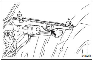
14. INSTALL FRONT BUMPER REINFORCEMENT SUBASSEMBLY

- Install the front bumper reinforcement sub-assembly
with the 6 bolts.
Torque: 50 N*m (510 kgf*cm, 37 ft.*lbf)
15. INSTALL FRONT BUMPER ENERGY ABSORBER
 Disassembly
1. REMOVE FRONT BUMPER ENERGY ABSORBER
2. REMOVE FRONT BUMPER REINFORCEMENT SUBASSEMBLY
Remove the 6 bolts and the front bumper
reinforcement sub-assembly.
3. REMOVE FRONT BUMPER SIDE SU ...
 Installation
1. INSTALL FRONT BUMPER ASSEMBLY
Push the front bumper onto the front of the vehicle
and engage the claws on the left and right sides of
the front bumper to install it as shown in the
il ...
Other materials:
Canceling the power back door system (vehicles with power
back door)
Turn the main switch off to disable
the power back door system.
Off
On*
*: The orange line at the top of the
switch indicates that the power
back door system is on.
Luggage compartment light
The luggage compartment light turns on
when the back door is opened with the
luggage ...
No. 2 Speaker with box
COMPONENTS
ON-VEHICLE INSPECTION
1. INSPECT NO.2 SPEAKER WITH BOX
HINT:
Remove interior parts so that the No.2 speaker with box
can be seen.
Check the speaker installation.
OK:
The speaker is securely installed.
If the result is not as specified, reinstall the No.2
s ...
System description
1. BRIEF DESCRIPTION
The CAN (Controller Area Network) is a serial data
communication system for real time application. It is
a vehicle multiplex communication system which
has a high communication speed (500 kbps) and
the ability to detect malfunctions.
By pairing the CANH and CANL bu ...
