Toyota Sienna Service Manual: Disassembly
1. HOLD VANE PUMP ASSEMBLY

(a) Using SST, hold the vane pump assembly in a vise.
SST 09630-00014 (09631-00132)
2. REMOVE POWER STEERING SUCTION PORT UNION

(a) Remove the bolt and the power steering suction port union from the vane pump front housing.
(b) Using a screwdriver, remove the O-ring from the power steering suction port union.
3. REMOVE POWER STEERING FLUID PRESSURE SWITCH
NOTICE: Perform this procedure only when the power steering fluid pressure switch is replaced.
(a) Remove the power steering fluid pressure switch from the vane pump front housing.
4. REMOVE FLOW CONTROL VALVE ASSEMBLY

(a) Remove the pressure port union from the vane pump front housing.
(b) Remove the O-ring from the pressure port union.
(c) Remove the flow control valve assembly and the flow control valve compression spring from the vane pump front housing.
5. REMOVE VANE PUMP REAR HOUSING

(a) Remove the 4 bolts and vane pump rear housing from the vane pump front housing.

(b) Using a screwdriver, remove the O-ring from the vane pump rear housing.
HINT: Tape the screwdriver tip before use.
6. REMOVE VANE PUMP SHAFT WITH PULLEY

(a) Using 2 screwdrivers, remove the vane pump shaft snap ring from the vane pump shaft with pulley.
(b) Remove the vane pump shaft with pulley.
7. REMOVE VANE PUMP ROTOR

(a) Remove the 10 vane pump plates.
(b) Remove the vane pump rotor.
8. REMOVE VANE PUMP CAM RING

(a) Remove the vane pump cam ring from the vane pump front housing.
9. REMOVE VANE PUMP FRONT SIDE PLATE

(a) Remove the vane pump front side plate from the vane pump front housing.

(b) Using a screwdriver, remove the O-ring from the vane pump front side plate.
HINT: Tape the screwdriver tip before use.
(c) Remove the O-ring from the vane pump front housing.
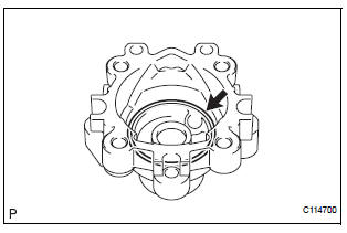
10. REMOVE VANE PUMP HOUSING OIL SEAL

(a) Using a screwdriver and a shop rag or a piece of cloth, remove the vane pump housing oil seal from the vane pump front housing.
NOTICE: Be careful not to damage the vane pump front housing.
 Removal
1. DRAIN POWER STEERING FLUID
2. REMOVE FRONT WHEEL RH
3. REMOVE FRONT FENDER APRON SEAL RH (See
page EM-26)
4. REMOVE FAN AND GENERATOR V BELT (See page
EM-6)
5. DISCONNECT NO. 1 FLUID RESERVOI ...
 Inspection
1. INSPECT VANE PUMP SHAFT AND BUSHING IN VANE PUMP FRONT HOUSING
(a) Using a micrometer, measure the outer diameter [a]
of the vane pump shaft with pulley.
(b) Using vernier calipers, measur ...
Other materials:
How to proceed with
troubleshooting
1 VEHICLE BROUGHT TO WORKSHOP
2 CUSTOMER PROBLEM ANALYSIS
3 CHECK AND CLEAR DTCs
Refer to the diagnostic check/clear
4 PROBLEM SYMPTOM CONFIRMATION
5 SYMPTOM SIMULATION
6 CHECK DTC
7 CHECK IF THE SAME SYMPTOM APPEARS IN THE NAVIGATION SYSTEM
Refer to the navigation system
8 PROBLE ...
Front Airbag Sensor LH Circuit Malfunction
DTC B1149/37 Front Airbag Sensor LH Circuit Malfunction
DESCRIPTION
The front airbag sensor LH circuit consists of the center airbag sensor
assembly and front airbag sensor
LH.
If the center airbag sensor assembly receives signals from the front airbag
sensor LH, it judges whether or
not ...
Inspection
1. INSPECT OUTER REAR VIEW MIRROR ASSEMBLY LH (w/o Memory)
Disconnect the mirror connector.
Check operation of the outer mirror.
Apply battery voltage and inspect operation of
the mirror face, as shown in the table and
illustration.
Standard (LH)
If the result i ...
