Toyota Sienna Service Manual: Television Display Assembly Communication Error
INSPECTION PROCEDURE
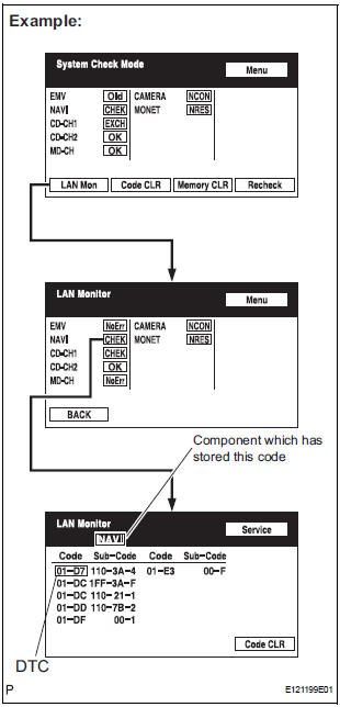
1 IDENTIFY THE COMPONENT SHOWN BY THE SUB-CODE
- Enter the diagnostic mode.
- Press the "LAN Mon" switch to change to "LAN Monitor" mode.
- Identify the component shown by the sub-code.
HINT:
- "110 (multi-display)" is the component shown by the sub-code in the example shown in the illustration.
- The sub-code will be indicated by its physical address.
- For the component list, refer to "DIAGNOSIS DISPLAY DETAILED DESCRIPTION"
2 CHECK POWER SOURCE CIRCUIT OF COMPONENT SHOWN BY SUB-CODE
- Inspect the power source circuit of the component shown
by the sub-code.
If the power source circuit is operating normally, proceed to the next step.
Component Table:

3 INSPECT RADIO AND NAVIGATION ASSEMBLY

- Disconnect the radio and navigation assembly connectors.
- Measure the resistance according to the value(s) in the table below.
Standard resistance

4 CHECK HARNESS AND CONNECTOR
HINT:
- Start the check from the circuit that is near the component shown by the sub-code first.
- For details of the connectors, refer to "TERMINALS OF ECU".
- Referring to the AVC-LAN wiring diagram below, check the AVC-LAN circuit between the television display assembly and the component shown by the sub-code.
- Disconnect all connectors between the television display assembly and the component shown by sub-code.
- Check for an open or short in the AVC-LAN circuit between the television display assembly and the component shown by the sub-code.

OK: There is no open or short circuit.
5 REPLACE COMPONENT SHOWN BY SUB-CODE
- Replace the component shown by the sub-code with a normal one and check if the same problem occurs again.
OK: Same problem does not occur
END
 Radio and Navigation Assembly Communication Error
INSPECTION PROCEDURE
1 IDENTIFY THE COMPONENT SHOWN BY THE SUB-CODE
Enter the diagnostic mode.
Press the "LAN Mon" switch to change to "LAN Monitor"
mode.
&nbs ...
 Stereo Component Amplifier Power Source Circuit
DESCRIPTION
This circuit provides power to the stereo component amplifier.
WIRING DIAGRAM
INSPECTION PROCEDURE
1 INSPECT STEREO COMPONENT AMPLIFIER
Disconnect the stereo component ampl ...
Other materials:
Repair
1. REPAIR REAR WINDOW DEFOGGER WIRE
Clean the broken wire tips with grease, wax and
silicone remover.
Place the masking tape along the both sides of the
wire.
Thoroughly mix the repair agent (Dupont paste No.
4817).
Using a fine tip brush, apply a smal ...
Disposal
HINT:
On the RH side, use the same procedures as on the LH side.
1. DISPOSE OF BACK DOOR STAY SUB-ASSEMBLY LH
Horizontally fix the stay in a vise with the piston-rod
pulled out.
Wearing safety glasses, gradually cut a part
between A and B as shown in the illustration using a
metal ...
Precaution
1. HANDLING PRECAUTION FOR CRUISE CONTROL
SYSTEM
Turn the cruise control main switch off when not
using the cruise control system.
Be careful as the vehicle speed increases when
driving downhill with the cruise control system on.
The + (ACCEL)/RES (RESUME) operation ch ...
