Toyota Sienna Service Manual: Radio and Navigation Assembly Communication Error
INSPECTION PROCEDURE
1 IDENTIFY THE COMPONENT SHOWN BY THE SUB-CODE
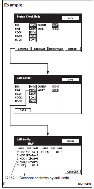
- Enter the diagnostic mode.
- Press the "LAN Mon" switch to change to "LAN Monitor" mode.
- Identify the component shown by the sub-code.
HINT:
- "110 (multi-display)" is the component shown by the sub-code in the example shown in the illustration.
- The sub-code will be indicated by its physical address.
- For the component list, refer to "DIAGNOSIS DISPLAY DETAILED DESCRIPTION"
2 CHECK POWER SOURCE CIRCUIT OF COMPONENT SHOWN BY SUB-CODE
- Inspect the power source circuit of the component shown
by the sub-code.
If the power source circuit is operating normally, proceed to the next step
Component Table:

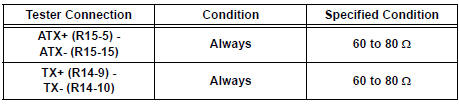
3 CHECK RADIO AND NAVIGATION ASSEMBLY
- Disconnect the radio and navigation assembly.
- Measure the resistance according to the value(s) in the table below.
Standard resistance
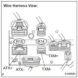
4 CHECK HARNESS AND CONNECTOR
HINT:
- Start the check from the circuit that is near the component shown by the sub-code first.
- For details of the connectors, refer to "TERMINALS OF ECU".
- Referring to the AVC-LAN wiring diagram below, check the AVC-LAN circuit between the radio and navigation assembly and the component shown by the sub-code.
- Disconnect all connectors between the radio and navigation assembly and the component shown by sub-code.
- Check for an open or short in the AVC-LAN circuit between the radio and navigation assembly and the component shown by the sub-code
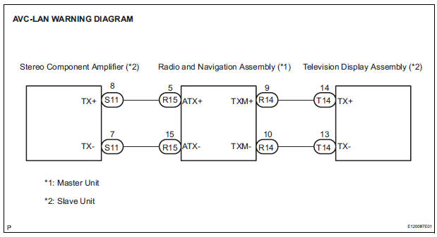
OK: There is no open or short circuit.
5 REPLACE COMPONENT SHOWN BY SUB-CODE
- Replace the component shown by the sub-code with a normal one and check if the same problem occurs again.
OK: Same problem does not occur.
END
 Stereo Component Amplifier Communication Error
INSPECTION PROCEDURE
1 IDENTIFY THE COMPONENT SHOWN BY THE SUB-CODE
Enter the diagnostic mode.
Press the "LAN Mon" switch to change to "LAN Monitor"
mode.
&nbs ...
 Television Display Assembly Communication Error
INSPECTION PROCEDURE
1 IDENTIFY THE COMPONENT SHOWN BY THE SUB-CODE
Enter the diagnostic mode.
Press the "LAN Mon" switch to change to "LAN Monitor"
mode.
&nbs ...
Other materials:
Power Slide Door does not Fully Open
DESCRIPTION
When the LH / RH rear window is open 105 mm (5.91 in.) or more,
the slide door half-open stopper is
activated to force the slide door to stop at approximately 105 mm (5.91 in.)
from the fully open position.
This is caused by the jam protection function between the sli ...
Terminals of ECU
1. CHECK POWER SLIDE DOOR ECU LH (WITH
POWER SLIDE DOOR)
Disconnect the P25 and P26 ECU connectors, and
check the voltage and resistance of each terminal of
the wire harness side connectors.
If the result is not as specified, there may be a
malfunction on the wire harness side.
...
Inspection
1. Inspect pack clearance of reverse clutch
(A) install the intermediate shaft and needle roller
bearing onto the transaxle rear cover.
(B) using a dial indicator, measure the reverse clutch
pack clearance while applying and releasing
compressed air (392 kpa, 4.0 Kgf/cm2, 57 psi).
Pack c ...
