Toyota Sienna Service Manual: Terminals of ecm
Sfi system

Hint:
The standard normal voltage between each pair of the ECM terminals is shown in the table below. The appropriate conditions for checking each pair of the terminals are also indicated.
The check results should be compared with the standard normal voltage for that pair of terminals, listed in the "Specified Condition" column.
The illustration above can be used as a reference to identify the ECM terminal locations.


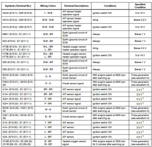
*1: The ECM terminal voltage is constant regardless of the output voltage from the sensor.

(a) WAVEFORM 1
(1) Camshaft Timing Oil Control Valve (OCV)
operation signal

HINT:
The wavelength becomes shorter as the engine rpm increases.

(b) WAVEFORM 2
(1) Heated oxygen sensor signal

HINT:
In the DATA LIST, item O2S B1S2 shows the ECM input values from the heated oxygen sensor.

(c) WAVEFORM 3
(1) Fuel injector operation signal

HINT:
The wavelength becomes shorter as the engine rpm increases.

(d) WAVEFORM 4
(1) Knock sensor signal

HINT:
- The wavelength becomes shorter as the engine rpm increases.
- The waveforms and amplitudes displayed differ slightly depending on the vehicle.

(e) WAVEFORM 5
(1) Variable Valve Timing (VVT) sensor signal (1)
(2) Crankshaft position sensor signal (2)

HINT:
The wavelength becomes shorter as the engine rpm increases.

(f) WAVEFORM 6
(1) Igniter IGT signal (from ECM to igniter) (1)
(2) Igniter IGF signal (from igniter to ECM) (2)

HINT:
The wavelength becomes shorter as the engine rpm increases.

(g) WAVEFORM 7
(1) Purge VSV for EVAP system operation signal

HINT:
If the waveform is not similar to that shown in the illustration, check the waveform again after idling for 10 minutes or more.

(h) WAVEFORM 8
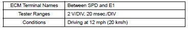
(1) Vehicle speed signal
HINT:
- The wavelength becomes shorter as the vehicle speed increases.
- Depending on the vehicle, the output waveform voltage may rise to 12 V if influenced by optionally installed systems.

(i) WAVEFORM 9
(1) Throttle drive motor operation signal (positive
terminal) 
HINT:
The duty ratio varies depending on the throttle actuator operation.

(j) WAVEFORM 10
(1) Throttle drive motor operation signal (negative
terminal) 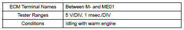

(k) WAVEFORM 11
1) Engine speed signal

HINT:
The wavelength becomes shorter as the engine rpm increases.
 Problem symptoms table
HINT:
When a malfunction is not confirmed by a DTC (Diagnostic
Trouble Code) check and the cause of problem cannot be
identified through a basic inspection, troubleshoot according
to the priority ...
 Diagnosis system
DESCRIPTION
(a) When troubleshooting OBD II (On-Board
Diagnostics) vehicles, an intelligent tester
(complying with SAE J1987) must be connected to
the DLC3 (Data Link Connector 3) of the vehicle.
...
Other materials:
Hydraulic test
1. Perform hydraulic test
(a) Measure the line pressure.
NOTICE:
Perform the test at the normal operating ATF
(Automatic Transmission Fluid) temperature:
50 to 80°C (122 to 176°F).
The line pressure test should always be
carried out in pairs. One technician should
...
Removal
HINT:
Use the same procedures for the RH side and LH side.
The procedures listed below are for the LH side.
1. PRECAUTION
CAUTION: Be sure to read "PRECAUTION" thoroughly before
servicing.
2. DISCONNECT CABLE FROM NEGATIVE BATTERY
TERMINAL
CAUTION:
Wait for 90 s ...
Removal
1. REMOVE BACK DOOR CENTER GARNISH
Using a clip remover, disengage the 5 clips to
remove the back door center garnish.
2. REMOVE REAR SPOILER
Disconnect the center stop light connector.
Remove the 3 nuts.
Using a clip remover, disengage the 2 clips to
remove the rear s ...
