Toyota Sienna Service Manual: ACC Power Source Circuit
DESCRIPTION
This circuit supplies power to the A/C amplifier and the illumination for the clock.
WIRING DIAGRAM

INSPECTION PROCEDURE
1 INSPECT FUSE (ECU ACC)
(a) Remove the ECU ACC fuse from the engine room relay block.
(b) Measure the resistance according to the value(s) in the table below.
Standard resistance 


2 CHECK HARNESS AND CONNECTOR (A/C AMPLIFIER - BATTERY)
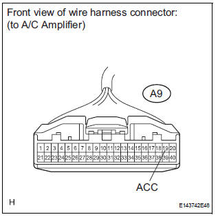
(a) Disconnect the connector from the A/C amplifier.
(b) Measure the voltage according to the value(s) in the table below.
Standard voltage 


PROCEED TO NEXT CIRCUIT INSPECTION SHOWN IN PROBLEM SYMPTOMS TABLE
 IG Power Source Circuit
DESCRIPTION
The main power source is supplied to the A/C amplifier when the ignition
switch is turned to the ON
position.
The power source is used for operating the A/C amplifier and servo moto ...
 Back-up Power Source Circuit
DESCRIPTION
This is the back-up power source for the A/C amplifier. Power is supplied
even when the ignition switch is
off and is used for diagnostic trouble code memory, etc.
WIRING DIAGRAM
...
Other materials:
Access monitor result
(A) select the following menus on the intelligent tester:
diagnosis, enhanced obdii, monitor info
and monitor result. The monitor status
appears after the component name.
INCMP: The component has not been monitored
yet.
PASS: The component is functioning normally.
FAIL: The component is ...
Throttle / Pedal Position Sensor/ Switch
DTC P2120 Throttle / Pedal Position Sensor / Switch "D"
Circuit
DTC P2122 Throttle / Pedal Position Sensor / Switch "D"
Circuit Low Input
DTC P2123 Throttle / Pedal Position Sensor / Switch "D"
Circuit High Input
DTC P2125 Throttle / Pedal Position Sensor / Switch ...
Removal
1. PRECAUTION
CAUTION:
Be sure to read "PRECAUTION" thoroughly before
servicing.
2. DISCONNECT CABLE FROM NEGATIVE BATTERY
TERMINAL
CAUTION:
Wait for 90 seconds after disconnecting the cable to
prevent the airbag working.
3. PLACE FRONT WHEELS FACING STRAIGHT AHEAD
4. REMOVE STEE ...