Toyota Sienna Service Manual: IG Power Source Circuit
DESCRIPTION
The main power source is supplied to the A/C amplifier when the ignition switch is turned to the ON position.
The power source is used for operating the A/C amplifier and servo motor, etc.
WIRING DIAGRAM

INSPECTION PROCEDURE
HINT: Start the engine before inspection. Check the IG1 relay or battery if the engine does not start.
1 INSPECT FUSE (HTR)
(a) Remove the HTR fuse from the driver side junction block.
(b) Measure the resistance according to the value(s) in the table below.
Standard resistance 


2 INSPECT A/C AMPLIFIER (IG - GND)

(a) Remove the A/C amplifier with its connectors still connected.
(b) Turn the ignition switch to the ON position.
(c) Measure the voltage according to the value(s) in the table below.
Standard voltage 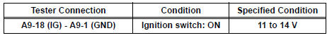


PROCEED TO NEXT CIRCUIT INSPECTION SHOWN IN PROBLEM SYMPTOMS TABLE
3 CHECK HARNESS AND CONNECTOR (A/C AMPLIFIER - BATTERY)

(a) Disconnect the connector from the A/C amplifier.
(b) Measure the voltage according to the value(s) in the table below.
Standard voltage


4 CHECK HARNESS AND CONNECTOR (A/C AMPLIFIER - BODY GROUND)

(a) Measure the resistance according to the value(s) in the table below.
Standard resistance 


REPLACE A/C AMPLIFIER
 Rear Blower Motor Circuit
DESCRIPTION
Power to the rear blower motor is supplied from the battery via the RR A/C
relay.
The rear blower motor speed level varies between 0 and 31 based on the voltage
difference measured ...
 ACC Power Source Circuit
DESCRIPTION
This circuit supplies power to the A/C amplifier and the illumination for the
clock.
WIRING DIAGRAM
INSPECTION PROCEDURE
1 INSPECT FUSE (ECU ACC)
(a) Remove the ECU ACC fuse fr ...
Other materials:
Disassembly
1. REMOVE SIDE DEFROSTER NOZZLE DUCT NO.1
(a) Remove the 2 screws <C> and defroster nozzle
duct No. 1.
2. REMOVE SIDE DEFROSTER NOZZLE DUCT NO.2
(a) Remove the 2 screws <C> and defroster nozzle
duct No. 2.
3. REMOVE DEFROSTER NOZZLE ASSEMBLY
(a) Remove the 4 screws <C> and d ...
Evaporative Emission System
DTC P043E Evaporative Emission System Reference Orifice
Clog Up
DTC P043F Evaporative Emission System Reference Orifice
High Flow
DTC P2401 Evaporative Emission System Leak Detection
Pump Control Circuit Low
DTC P2402 Evaporative Emission System Leak Detection
Pump Control Circuit High
DTC P ...
Oxygen (A/F) Sensor Pumping Current Circuit
DTC P2238 Oxygen (A/F) Sensor Pumping Current Circuit
Low (Bank 1 Sensor 1)
DTC P2239 Oxygen (A/F) Sensor Pumping Current Circuit
High (Bank 1 Sensor 1)
DTC P2241 Oxygen (A/F) Sensor Pumping Current Circuit
Low (Bank 2 Sensor 1)
DTC P2242 Oxygen (A/F) Sensor Pumping Current Circuit
High (Bank ...