Toyota Sienna Service Manual: Air Mix Damper Position Sensor Circuit (Driver Side)
DESCRIPTION
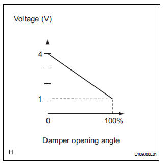
This sensor detects the position of the air mix control servo motor (air outlet damper) and sends the appropriate signals to the A/C amplifier. The position sensor is built in the air mix control servo motor. The position sensor resistance changes as the air mix control servo motor arm moves.
It outputs voltage (5 V) that is input to terminal 1 and terminal 3 via the
variable resistor, and then to the A/
C amplifier. The A/C amplifier determines the arm position based on the input
voltage from the position
sensor.
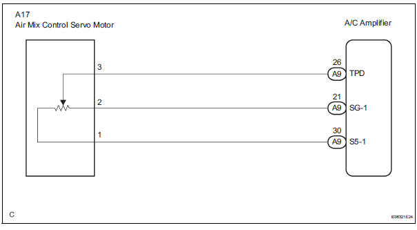
WIRING DIAGRAM
INSPECTION PROCEDURE
1 READ VALUE OF INTELLIGENT TESTER
(a) Connect the intelligent tester to the DLC3.
(b) Turn the ignition switch to the ON position and turn the intelligent tester main switch on.
(c) Select the items below in the DATA LIST, and read the display on the intelligent tester.
DATA LIST / AIR CONDITIONER 
OK: The display is as specified in the normal condition column.
Result 


2 INSPECT AIR MIX CONTROL SERVO MOTOR
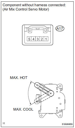
(a) Remove the air mix control servo motor.
(b) Disconnect the connector from the air mix control servo motor.
(c) Measure the resistance according to the value(s) in the table below.
Standard resistance 
(d) Measure the resistance according to the value(s) in the table below.
Standard resistance 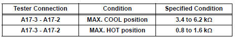
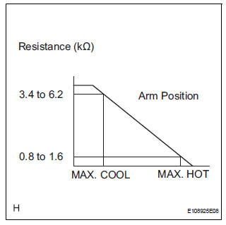
(e) As the air mix control servo motor moves from the COOL side to the HOT side, the resistance decreases gradually without interruption.


3 CHECK HARNESS AND CONNECTOR (AIR MIX CONTROL SERVO MOTOR - A/C AMPLIFIER)

(a) Disconnect the connector from the A/C amplifier.
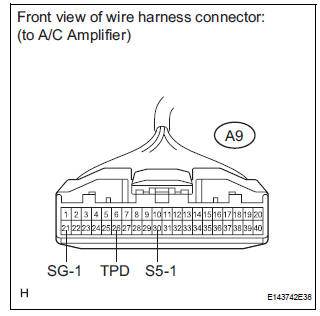
(b) Measure the resistance according to the value(s) in the table below.
Standard resistance 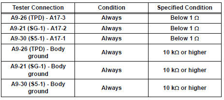

REPLACE A/C AMPLIFIER
 Air Outlet Damper Position Sensor Circuit
DESCRIPTION
This sensor detects the position of the air outlet control servo motor and
sends the appropriate signals to
the A/C amplifier. The position sensor is built in the air outlet contro ...
 Rear Air Mix Damper Position Sensor Circuit
DESCRIPTION
This sensor detects the position of the rear air mix control servo motor
(water valve servo motor) and
sends the appropriate signals to the A/C amplifier. The position sensor is bu ...
Other materials:
Master Reset/ Voice Processing Device ON Error
DTC 01-DD Master Reset
DTC 01-E1 Voice Processing Device ON Error
DESCRIPTION
HINT:
*1: This code may be stored if the engine is started and the ignition switch is
turned to START position
again.
*2: Even if no fault is present, this trouble code may be stored depending on
the battery ...
CD Abnormal/ Excess Current/ Tray Insertion / Ejection Error/ CD Abnormal/
Excess Current/ Tray Insertion / Ejection Error
DTC 62-44 CD Abnormal
DTC 62-48 Excess Current
DTC 62-50 Tray Insertion / Ejection Error
DTC 63-44 CD Abnormal
DTC 63-48 Excess Current
DTC 63-50 Tray Insertion / Ejection Error
DESCRIPTION
DTC No.
DTC Detecting Condition
Trouble Area
62-44
Operation error ...
Transmission Range Sensor Circuit Malfunction
(PRNDL Input)
DESCRIPTION
The park/neutral position switch detects the shift lever position and sends
signals to the ECM.
MONITOR DESCRIPTION
These DTCs indicate a problem with the park/neutral position switch and the
wire harness in the park/
neutral position switch circuit.
The park/neutral po ...