Toyota Sienna Service Manual: Rear Air Mix Damper Position Sensor Circuit
DESCRIPTION

This sensor detects the position of the rear air mix control servo motor (water valve servo motor) and sends the appropriate signals to the A/C amplifier. The position sensor is built in the rear air mix control servo motor (water valve servo motor).
The position sensor's resistance changes as the rear air mix control servo motor valve moves.
It outputs voltage (5 V) that is input to terminal 2 and terminal 3 via the variable resistor, and then to the A/ C amplifier.
The A/C amplifier determines the valve position based on the input voltage from
the position sensor.
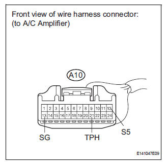
WIRING DIAGRAM

INSPECTION PROCEDURE
1 READ VALUE OF INTELLIGENT TESTER
(a) Connect the intelligent tester to the DLC3.
(b) Turn the ignition switch to the ON position and turn the intelligent tester main switch on.
(c) Select the items below in the DATA LIST, and read the display on the intelligent tester.
DATA LIST / AIR CONDITIONER 
OK: The display is as specified in the normal condition column.
Result 


2 INSPECT REAR AIR MIX CONTROL SERVO MOTOR (WATER VALVE SERVO MOTOR)

(a) Remove the rear air mix control servo motor (water valve servo motor).
(b) Disconnect the connector from the rear air mix control servo motor (water valve servo motor).
(c) Measure the resistance according to the value(s) in the table below.
Standard resistance
(d) Measure the resistance according to the value(s) in the table below.
HINT
- In order to turn the motor to the "MAX. COOL" position, connect the positive (+) lead to terminal 5, and the negative (-) lead to terminal 4.
- In order to turn the motor to the "MAX. HOT" position, connect the positive (+) lead to terminal 4, and the negative (-) lead to terminal 5.
Standard resistance 

(e) As the rear air mix control servo motor (water valve servo motor) moves from the cool side to the hot side, the resistance decreases gradually without interruption.


3 CHECK HARNESS AND CONNECTOR (REAR AIR MIX CONTROL SERVO MOTOR - A/C AMPLIFIER)

(a) Disconnect the connector from the A/C amplifier.
(b) Measure the resistance according to the value(s) in the table below.
Standard resistance 


REPLACE A/C AMPLIFIER
 Air Mix Damper Position Sensor Circuit (Driver Side)
DESCRIPTION
This sensor detects the position of the air mix control servo motor (air
outlet damper) and sends the
appropriate signals to the A/C amplifier. The position sensor is built in the ...
 Rear Air Outlet Damper Position Sensor Circuit
DESCRIPTION
This sensor detects the position of the rear air outlet control servo motor
and sends the appropriate
signals to the A/C amplifier. The position sensor is built in the rear air
o ...
Other materials:
Touch screen gestures
Operations are performed by touching the screen directly with your
finger.
Operation method
Outline
Main use
Touch
Quickly touch and
release once.
Changing and selecting
various settings.
Drag*
Touch the screen
with your ...
Installation
1. INSTALL WINDSHIELD GLASS NO.2 STOPPER
Coat the installation part of the stoppers with Primer
G.
NOTICE:
Allow the primer coating to dry for 3 minutes
or more.
Do not keep any of the opened Primer G for
later use.
Do not apply too much Primer .
...
Disposal
HINT:
Use the same procedures for the RH side and LH side.
The procedures listed below are for the LH side.
When scrapping a vehicle equipped with the SRS or
disposing of the front seat side airbag assembly, be sure to
deploy the airbag first in accordance with the proc ...