Toyota Sienna Service Manual: Back Sonar Sensor LH Circuit
DESCRIPTION
An ultrasonic sensor consists of a sensor portion that transmits and receives ultrasonic waves and a preamplifier that amplifies them. The ultrasonic sensor outputs the ultrasonic waves and sends the received signals to the clearance warning ECU.
WIRING DIAGRAM

INSPECTION PROCEDURE
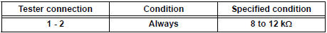
1 INSPECT NO. 2 ULTRASONIC SENSOR

- Remove the No. 2 ultrasonic sensor.
- Measure the resistance according to the value(s) in the table below.
Standard resistance
2 CHECK HARNESS AND CONNECTOR (CLEARANCE WARNING ECU - NO. 2 ULTRASONIC SENSOR)

- Disconnect the C9 connector from the clearance warning ECU.

- Disconnect the U3 connector from the No. 2 ultrasonic sensor.
- Measure the resistance according to the value(s) in the table below.
Standard resistance

PROCEED TO NEXT CIRCUIT INSPECTION SHOWN IN PROBLEM SYMPTOMS TABLE
 Speed Signal Circuit
DESCRIPTION
The clearance warning ECU receives the vehicle speed signal from the
combination meter.
HINT:
A voltage of 12 V or 5 V is output from each ECU and then input to
the combin ...
 Back Sonar Sensor RH Circuit
DESCRIPTION
An ultrasonic sensor consists of a sensor portion that transmits and receives
ultrasonic waves and a preamplifier
that amplifies them. The ultrasonic sensor outputs the ultrasonic wave ...
Other materials:
Inspection
1. INSPECT OIL PUMP RELIEF VALVE
(a) Coat the relief valve with engine oil and check that it
falls smoothly into the valve hole under its own
weight.
If the valve does not fall smoothly, replace the relief
valve. If necessary, replace the oil pump assembly.
2. INSPECT OIL PUMP ROTOR SET
...
Adjustment
1. INSPECT SHIFT LEVER POSITION
(a) When shifting from P to R position only with ignition
switch ON and brake pedal, make sure that the
shifting lever moves smoothly and can be
moderately operated.
(b) When starting engine, make sure that the vehicle
moves forward when shifting from N to D p ...
Engine compartment
Items
Check points
Battery
Check connections
Brake fluid
Is the brake fluid at the correct level?
Engine coolant
Is the engine coolant at the correct
level?
Engine oil
Is the engine oil at the correct level?
Exhaust system ...