Toyota Sienna Service Manual: Speed Signal Circuit
DESCRIPTION
The clearance warning ECU receives the vehicle speed signal from the combination meter.
HINT:
- A voltage of 12 V or 5 V is output from each ECU and then input to the combination meter. The signal is changed to a pulse signal at the transistor in the combination meter. Each ECU controls the respective system based on the pulse signal.
- If a short occurs in an ECU, all systems in the diagram below will not operate normally.
WIRING DIAGRAM

INSPECTION PROCEDURE
1 CHECK OPERATION OF SPEEDOMETER
- Drive the vehicle and check if the function of the speedometer in the combination meter is normal.
OK: Actual vehicle speed and the speed indicated on the speedometer are the same.
HINT: The vehicle speed signal is normal when the indication on the speedometer is normal.
2 INSPECT CLEARANCE WARNING ECU

- Disconnect the clearance warning ECU connector C9.
- Measure the voltage.
- Jack up either one of the drive wheels.
- Move the shift lever to the neutral position.
- Turn the ignition switch to the ON position

- Measure the voltage between terminal SPD of the clearance warning ECU and body ground when a drive wheel is turned slowly.
OK: Voltage pulses as shown.
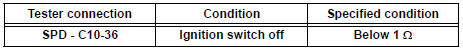
3 CHECK HARNESS AND CONNECTOR (COMBINATION METER - CLEARANCE WARNING ECU)

- Disconnect the combination meter C10 connector.
- Measure the resistance according to the value(s) in the table below.
Standard resistance
4 CHECK HARNESS AND CONNECTOR (COMBINATION METER AND EACH ECU - BODY GROUND)

- Measure the resistance according to the value(s) in the table below.
Standard resistance

HINT: If the resistance between terminal SPD and body ground is less than 10 kΩ, there may be a short in a wire harness, connector, or ECU.
REPLACE COMBINATION METER
 Park / Neutral Position Switch Circuit
DESCRIPTION
The clearance warning ECU receives the reverse or park position signal from
the park / neutral position
switch.
WIRING DIAGRAM
INSPECTION PROCEDURE
1 INSPECT CLEARANCE WARNING E ...
 Back Sonar Sensor LH Circuit
DESCRIPTION
An ultrasonic sensor consists of a sensor portion that transmits and receives
ultrasonic waves and a preamplifier
that amplifies them. The ultrasonic sensor outputs the ultrasonic wave ...
Other materials:
Engine Coolant Temperature Receiver Gauge Malfunction
DESCRIPTION
The meter CPU receives engine coolant temperature signals from the ECM via
the multiplex
communication lines. The meter CPU displays engine coolant temperature that is
calculated based on the
data received from the ECM.
WIRING DIAGRAM
INSPECTION PROCEDURE
HINT:
If there is ...
Transmitter battery
REPLACEMENT
1. REMOVE TRANSMITTER BATTERY
NOTICE:
Special caution should be taken for handling each
component as they are precision electronic
components.
Using a coin or the equivalent, pry out the
transmitter case.
NOTICE:
Do not forcibly pry out the case.
Re ...
Installation
1. Install air fuel ratio sensor (for bank 2
sensor 1)
(a) Using SST, install the sensor to the exhaust
manifold LH.
SST 09224-00010
Torque: 40 N*m (408 kgf*cm, 30 ft.*lbf) for use
with SST
44 N*m (449 kgf*cm, 32 ft.*lbf) for use
without SST
HINT:
Use a torque wrench with a fulcrum ...