Toyota Sienna Service Manual: Center Airbag Sensor Assembly Malfunction
DTC B1100/31 Center Airbag Sensor Assembly Malfunction
DESCRIPTION
The center airbag sensor assembly consists of the center airbag sensor assembly, safing sensor, drive circuit, diagnosis circuit and ignition control, etc.
It receives signals from the airbag sensor, judges whether or not the SRS must be activated, and detects diagnosis system malfunction.
DTC B1100/31 is recorded when a malfunction is detected in the center airbag sensor assembly circuit.

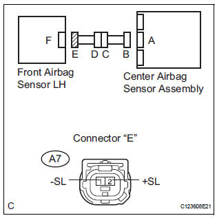
WIRING DIAGRAM

INSPECTION PROCEDURE
HINT: When a trouble code is displayed simultaneously with B1100/31, repair the malfunction indicated by this code (except B1100/31) first.
1 CHECK FRONT AIRBAG SENSOR RH CIRCUIT (SHORT TO GROUND)

- Turn the ignition switch to the LOCK position.
- Disconnect the negative (-) terminal cable from the battery, and wait for at least 90 seconds.
- Disconnect the connectors from the front airbag sensor RH and the center airbag sensor assembly.
- Measure the resistance according to the value(s) in the table below.
Standard resistance

2 CHECK FRONT AIRBAG SENSOR RH CIRCUIT (SHORT TO B+)

- Connect the negative (-) terminal cable to the battery, and wait for at least 2 seconds.
- Turn the ignition switch to the ON position.
- Measure the voltage according to the value(s) in the table below.
Standard voltage

3 CHECK FRONT AIRBAG SENSOR RH CIRCUIT (SHORT)

- Turn the ignition switch to the LOCK position.
- Disconnect the negative (-) terminal cable from the battery, and wait for at least 90 seconds.
- Measure the resistance according to the value(s) in the table below.
Standard resistance

4 CHECK FRONT AIRBAG SENSOR LH CIRCUIT (SHORT TO GROUND)

- Disconnect the connector from the front airbag sensor LH.
- Measure the resistance according to the value(s) in the table below.
Standard resistance

5 CHECK FRONT AIRBAG SENSOR LH CIRCUIT (SHORT TO B+)
- Connect the negative (-) terminal cable to the battery, and wait for at least 2 seconds.
- Turn the ignition switch to the ON position.
- Measure the voltage according to the value(s) in the table below.
Standard voltage

6 CHECK FRONT AIRBAG SENSOR LH CIRCUIT (SHORT)

- Turn the ignition switch to the LOCK position.
- Disconnect the negative (-) terminal cable from the battery, and wait for at least 90 seconds.
- Measure the resistance according to the value(s) in the table below.
Standard resistance

7 CHECK CENTER AIRBAG SENSOR ASSEMBLY

- Connect the connectors to the center airbag sensor assembly, front airbag sensors RH and LH.
- Connect the negative (-) terminal cable to the battery, and wait for at least 2 seconds.
- Turn the ignition switch to the ON position, and wait for at least 60 seconds.
- Clear the DTCs stored in memory.
- Turn the ignition switch to the LOCK position.
- Turn the ignition switch to the ON position, and wait for at least 60 seconds.
- Check the DTCs.
OK: DTC B1100/31 is not output.
USE SIMULATION METHOD TO CHECK
8 CHECK ENGINE ROOM MAIN WIRE (SHORT TO GROUND)

- Disconnect the engine room main wire connector from the instrument panel wire.
- Measure the resistance according to the value(s) in the table below.
Standard resistance

REPAIR OR REPLACE INSTRUMENT PANEL WIRE
9 CHECK ENGINE ROOM MAIN WIRE (SHORT TO B+)

- Turn the ignition switch to the LOCK position.
- Disconnect the negative (-) terminal cable from the battery, and wait for at least 90 seconds.
- Disconnect the engine room main wire connector from the instrument panel wire.
- Connect the negative (-) terminal cable to the battery, and wait for at least 2 seconds.
- Turn the ignition switch to the ON position.
- Measure the voltage according to the value(s) in the table below.
Standard voltage

REPAIR OR REPLACE INSTRUMENT PANEL WIRE
10 CHECK ENGINE ROOM MAIN WIRE (SHORT)

- Disconnect the engine room main wire connector from the instrument panel wire.
- Measure the resistance according to the value(s) in the table below.
Standard resistance

REPAIR OR REPLACE INSTRUMENT PANEL WIRE
11 CHECK ENGINE ROOM MAIN WIRE (SHORT TO GROUND)

- Disconnect the engine room main wire connector from the instrument panel wire.
- Measure the resistance according to the value(s) in the table below.
Standard resistance

REPAIR OR REPLACE INSTRUMENT PANEL WIRE
12 CHECK ENGINE ROOM MAIN WIRE (SHORT TO B+)

- Turn the ignition switch to the LOCK position.
- Disconnect the negative (-) terminal cable from the battery, and wait for at least 90 seconds.
- Disconnect the engine room main wire connector from the instrument panel wire.
- Connect the negative (-) terminal cable to the battery, and wait for at least 2 seconds.
- Turn the ignition switch to the ON position.
- Measure the voltage according to the value(s) in the table below.
Standard voltage

REPAIR OR REPLACE INSTRUMENT PANEL WIRE
13 CHECK ENGINE ROOM MAIN WIRE (SHORT)

- Disconnect the engine room main wire connector from the instrument panel wire.
- Measure the resistance according to the value(s) in the table below.
Standard resistance

REPAIR OR REPLACE INSTRUMENT PANEL WIRE
 Short to B+ in Front Pretensioner Squib LH Circuit
DTC B0138/72 Short to B+ in Front Pretensioner Squib LH Circuit
DESCRIPTION
The front pretensioner squib LH circuit consists of the center airbag sensor
assembly and the front seat
outer belt ass ...
 Half Connection in Center Airbag Sensor
Assembly Connectors
Half Connection in Center Airbag Sensor
Assembly Connectors
DTC B1135/24 Half Connection in Center Airbag Sensor
Assembly Connectors
DESCRIPTION
The center airbag sensor assembly connector has a mechanism that electrically
detects half connection.
The ...
Other materials:
Write vin
(a) The VIN writing process is shown in the flowchart
below. This process allows the VIN to be input into
the ECM. If the ECM is changed, or the ECM VIN
and Vehicle VIN do not match, the VIN can be
registered, or overwritten in the ECM by following
this procedure.
(b) Write VIN using the int ...
How to proceed with
troubleshooting
HINT:
Use this procedure to troubleshoot the front power seat
control system.
The intelligent tester should be used in steps 3 and 5.
1 VEHICLE BROUGHT TO WORKSHOP
2 CUSTOMER PROBLEM ANALYSIS CHECK AND PROBLEM SYMPTOM CHECK
3 CHECK COMMUNICATION FUNCTION OF MULTIPLEX COMMUNI ...
Installation
1. INSTALL REAR DOOR GLASS WEATHERSTRIP
Install the rear door glass weatherstrip.
2. INSTALL SLIDE DOOR WINDOW ASSEMBLY
3. INSTALL REAR DOOR GLASS RUN
4. INSTALL REAR DOOR TRIM BOARD SUBASSEMBLY
5. INSTALL SIDE TRIM BOARD COVER REAR
6. INSTALL REAR DOOR WINDOW FRAME SUBASSEMBLY
7. INSTA ...