Toyota Sienna Service Manual: Combination Meter ECU Communication Stop
DTC B1271 Combination Meter ECU Communication Stop
DESCRIPTION
DTC B1271 is output when communication between the combination meter and the multiplex network gateway ECU stops for more than 10 seconds.
|
DTC No. |
DTC Detection Condition |
Trouble Area |
|
B1271 |
Combination meter communication stops |
|
WIRING DIAGRAM

INSPECTION PROCEDURE
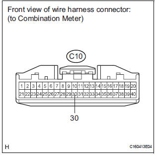
1 CHECK HARNESS AND CONNECTOR (COMBINATION METER - BATTERY)

- Disconnect the C10 connector.
- Measure the voltage according to the value(s) in the table below.
Standard voltage

2 CHECK HARNESS AND CONNECTOR (COMBINATION METER - GROUND)
- Measure the resistance according to the value(s) in the table below.
Standard resistance

3 CHECK COMMUNICATION LINE

- Disconnect the A9 and G4 connectors.
- Measure the resistance according to the value(s) in the table below.
Standard resistance

HINT:
*1: for Automatic A/C
*2: for Manual A/C
Result

REPLACE COMBINATION METER
 A/C ECU Communication Stop
DTC B1262 A/C ECU Communication Stop
DESCRIPTION
DTC B1262 is output when communication between the A/C amplifier and the
multiplex network gateway
ECU stops for more than 10 seconds.
...
 Power Seat ECU Communication Stop
DTC B1272 Power Seat ECU Communication Stop
DESCRIPTION
This DTC is detected when communication between the seat position control ECU
and the multiplex
network gateway ECU stops for more than 10 ...
Other materials:
TRAC OFF Indicator Light does not Come ON
DESCRIPTION
The skid control ECU is connected to the combination meter via CAN and
multiplex communications.
When the traction OFF switch is turned on, the TRAC OFF indicator light will
come on (for 2WD model).
WIRING DIAGRAM
Refer to TRAC OFF Indicator Light Remains ON (See page BC-157).
...
Short to GND in Rear Curtain Shield Squib LH
Circuit
DTC B1637/85 Short to GND in Rear Curtain Shield Squib LH
Circuit
DESCRIPTION
The rear curtain shield squib LH circuit consists of the center airbag sensor
assembly and the curtain
shield airbag assembly LH.
The circuit instructs the SRS to deploy when deployment conditions are met.
DTC ...
Removal
1. REMOVE REAR SEAT LEG SIDE GARNISH SUBASSEMBLY RH
Disengage the clips and remove the seat leg side
garnish sub-assembly RH.
2. REMOVE REAR NO. 2 SEAT ASSEMBLY RH
Remove the bolt and locus cable RH.
Remove the 2 bolts and rear No. 2 seat assembly
RH.
R ...