Toyota Sienna Service Manual: Power Seat ECU Communication Stop
DTC B1272 Power Seat ECU Communication Stop
DESCRIPTION
This DTC is detected when communication between the seat position control ECU and the multiplex network gateway ECU stops for more than 10 seconds.
|
DTC No. |
DTC Detection Condition |
Trouble Area |
|
B1272 |
Power seat ECU communication stops |
|
WIRING DIAGRAM

INSPECTION PROCEDURE
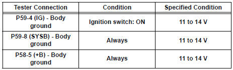
1 CHECK HARNESS AND CONNECTOR (SEAT POSITION CONTROL ECU - BATTERY)
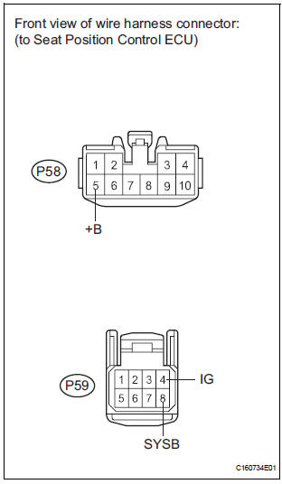
- Disconnect the P58 and P59 ECU connectors.
- Measure the voltage according to the value(s) in the table below.
Standard voltage
2 CHECK HARNESS AND CONNECTOR (SEAT POSITION CONTROL ECU - GROUND)

- Measure the resistance according to the value(s) in the table below.
Standard resistance

3 CHECK COMMUNICATION LINE
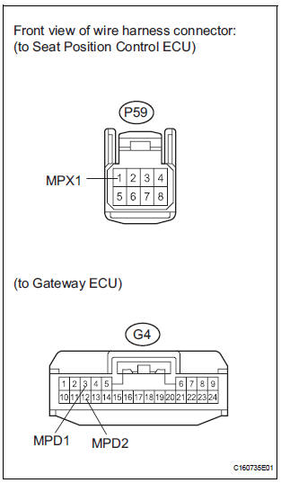
- Disconnect the G4 ECU connector.
- Measure the resistance according to the value(s) in the table below.
Standard resistance

Result

REPLACE SEAT POSITION CONTROL ECU
 Combination Meter ECU Communication Stop
DTC B1271 Combination Meter ECU Communication Stop
DESCRIPTION
DTC B1271 is output when communication between the combination meter and the
multiplex network
gateway ECU stops for more than 10 se ...
 Airbag ECU Communication Stop
DTC B1281 Airbag ECU Communication Stop
DESCRIPTION
DTC B1281 is output when communication between the airbag ECU and the
multiplex network gateway
ECU stops for more than 10 seconds.
...
Other materials:
DVD Error/ Excess Current/ Tray Insertion / Ejection Error
DTC 44-44 DVD Error
DTC 44-48 Excess Current
DTC 44-50 Tray Insertion / Ejection Error
DESCRIPTION
DTC No.
DTC Detection Condition
Trouble Area
44-44
Operation error in the DVD mechanism
Television display assembly
44-48
Excess current is prese ...
Knock Sensor 1 Circuit Low Input
DESCRIPTION
A flat type knock sensor (non-resonant type) has a structure that can detect
vibrations over a wide band of
frequencies: between approximately 6 kHz and 15 kHz.
Knock sensors are fitted onto the engine block to detect engine knocking.
The knock sensor contains a piezoelectr ...
On-vehicle inspection
1. INSPECT COOLER CONDENSER CORE
(a) If the fin of the cooler condenser core is dirty, clean
it with water and dry it with compressed air.
NOTICE:
Do not damage the fin of the cooler condenser
core.
(b) If the fin of the cooler condenser core is bent, make
it straight using a screwdriver or p ...