Toyota Sienna Service Manual: Diagnosis system
1. BUS CHECK

- Select "BUS CHECK" from the "OBD/MOBD MENU" screen.
HINT: The ECUs and sensors that are properly connected to the CAN communication system can be displayed using the intelligent tester via the CAN VIM.

- Press "ENTER" on the intelligent tester.

- The screen displays the ECUs and sensors that are properly connected to the CAN communication system.
HINT: Properly connected ECUs or sensors that are not displayed on the screen indicate that a communication stop is occuring in the system, sensor, or ECU which is not displayed.
2. CHECK FOR INSTALLED SYSTEMS (ECUS AND SENSORS) THAT USE CAN COMMUNICATION
- Systems (ECUs, sensors) that use CAN communication vary depending on the vehicle's optional equipment. Check which systems (ECUs, sensors) are installed on the vehicle.

HINT:
- *1: with VSC
- *2: with Dynamic laser cruise control
3. DTC TABLE BY ECU
HINT:
- For the CAN communication system, CAN communication system DTCs stored in certain ECUs can be displayed using the intelligent tester.
- If CAN communication system DTCs are output,
trouble cannot be determined only by the DTCs.
Perform troubleshooting according to "CHECK CAN BUS LINE" (See page CA-35).
- Skid control ECU (with VSC)
HINT: DTC communication uses the CAN communication system.

- ECM (with Dynamic laser cruise control)
HINT:
- DTC communication uses the CAN communication system.
- Distance control ECU data is output.
- Displayed on the "communication malfunction DTCs" screen of the intelligent tester. If U0235 or U1102 is output alone, the CAN communication is normal

- Gateway ECU
HINT: The network gateway ECU is connected to the CAN communication system, but CAN communication DTCs are not output.
4. DTCS COMBINATION TABLE
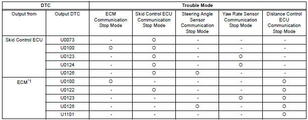
HINT: *1: with Dynamic laser cruise control
 Terminals of ECU
1. JUNCTION CONNECTOR
Junction connector
with VSC
HINT:
*1: with Dynamic laser cruise control
without VSC
CAN junction connector (with VSC)
with VSC
The connection ...
 Fail-safe chart
1. FAIL-SAFE FUNCTION
When communication fails in any of the main wires
(communication lines) due to a short circuit or other
causes, the fail-safe function, which is specified for
each syst ...
Other materials:
Terminals of ECU
1. MULTIPLEX NETWORK GATEWAY ECU
Disconnect the G4 ECU connector.
Measure the voltage between the specified
terminals on the wire harness side connector.
If the result is not as specified, there may be a
malfunction on the wire harness side.
Measure the resistance between ...
Communication Error from Distance Control
ECU to ECM
DTC P1615 Communication Error from Distance Control
ECU to ECM
DTC U1101 Lost Communication with Distance Control
ECU
DESCRIPTION
The distance control ECU receives information about the area in front of the
vehicle from the laser sensor
and then sends a brake control demand signal (decelerat ...
Suspension
SERVICE DATA
A: Ground clearance of front wheel center
B: Ground clearance of lower suspension arm No. 2 set bolt
center
C: Ground clearance of rear axle carrier bush set bolt center
D: Ground clearance of rear wheel center
TORQUE SPECIFICATIONS
TIRE AND WHEEL
SERVICE DATA
T ...