Toyota Sienna Service Manual: Terminals of ECU
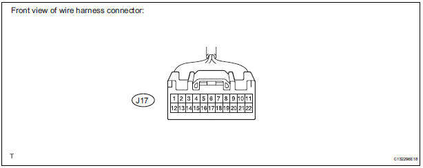
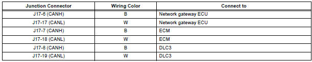
1. JUNCTION CONNECTOR
- Junction connector
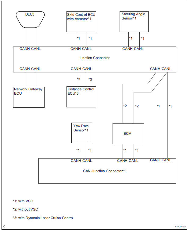
with VSC

HINT: *1: with Dynamic laser cruise control
without VSC
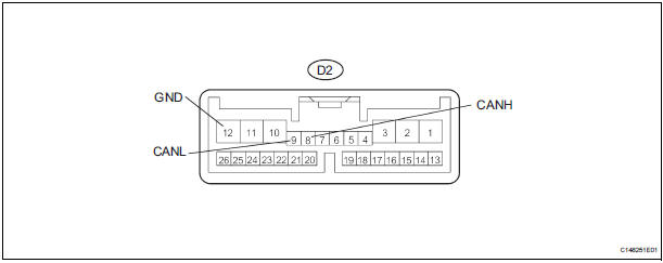
- CAN junction connector (with VSC)
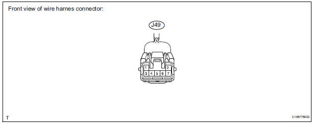
with VSC

- The connection diagram of the components which are connected to the CAN junction connector.
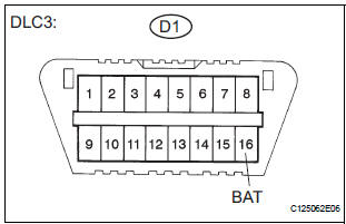
2. DLC3

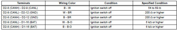
- Measure the resistance according to the value(s) in the table below.
Standard resistance

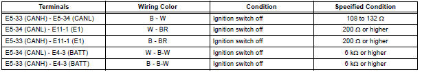
3. ECM
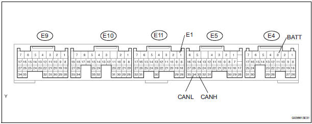
- Disconnect the connector from the ECM.
- Measure the resistance according to the value(s) in the table below
Standard resistance
4. NETWORK GATEWAY ECU

- Disconnect the connector from the netwark gateway ECU.
- Measure the resistance according to the value(s) in the table below
Standard resistance

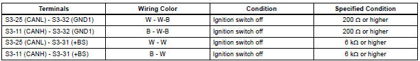
5. SKID CONTROL ECU WITH ACTUATOR

- Disconnect the connector from the skid control ECU with actuator.
- Measure the resistance according to the value(s) in the table below
Standard resistance

6. STEERING ANGLE SENSOR

- Disconnect the connector from the steering angle sensor.
- Measure the resistance according to the value(s) in the table below.
Standard resistance

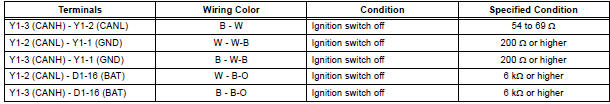
7. YAW RATE SENSOR

- Disconnect the connector from the yaw rate sensor.
- Measure the resistance according to the value(s) in the table below.
Standard resistance
8. DISTANCE CONTROL ECU
- Disconnect the connector from the distance control ECU.
- Measure the resistance according to the value(s) in the table below.
Standard resistance
 Problem symptoms table
RESULT LIST OF CHECK CAN BUS LINE
Symptom
Suspected Area
All ECUs and sensors connected to the CAN
communication system are not displayed on intelligent
tester
CAN ...
 Diagnosis system
1. BUS CHECK
Select "BUS CHECK" from the "OBD/MOBD
MENU" screen.
HINT:
The ECUs and sensors that are properly connected
to the CAN communication system can be displaye ...
Other materials:
Check mode procedure
1. CHECK MODE (SIGNAL CHECK): DTC CHECK
Connect the intelligent tester to the DLC3.
) Turn the ignition switch to the ON position.
) Select the "SIGNAL CHECK", and proceed
checking using the intelligent tester.
NOTICE:
Select the "SIGNAL CHECK" from the &q ...
Stereo component amplifier
COMPONENTS
Removal
1. REMOVE GLOVE COMPARTMENT DOOR ASSEMBLY
2. REMOVE STEREO COMPONENT AMPLIFIER ASSEMBLY
Disconnect the connectors.
Remove the 2 nuts and the stereo component
amplifier assembly.
Installation
1. INSTALL STEREO COMPONENT AMPLIFIER ASSEMBLY
...
Power back door touch sensor
INSPECTION
1. INSPECT POWER BACK DOOR TOUCH SENSOR LH
Check the resistance of the sensor.
Resistance
If the result is not as specified, replace the sensor.
2. INSPECT POWER BACK DOOR TOUCH SENSOR RH
Check the resistance of the sensor.
Resistance
If the result is not as ...