Toyota Sienna Service Manual: DTC check / clear
1. DTC CHECK (USING SST CHECK WIRE)
- Check the DTCs (Present trouble code).
- Turn the ignition switch ON, and wait for approximately 60 seconds.
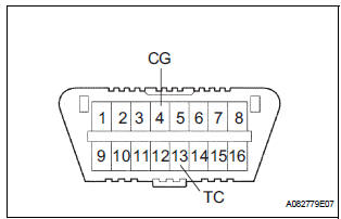
- Using SST, connect terminals TC and CG of the DLC3.
SST 09843-18040
NOTICE: Connect the terminals to the correct positions to avoid a malfunction.
- Check the DTCs (Past trouble code).
- Using SST, connect terminals TC and CG of the
DLC3.
SST 09843-18040
NOTICE: Connect the terminals to the correct positions to avoid a malfunction. - Turn the ignition switch ON, and wait for approximately 60 seconds.
- Read the DTCs.
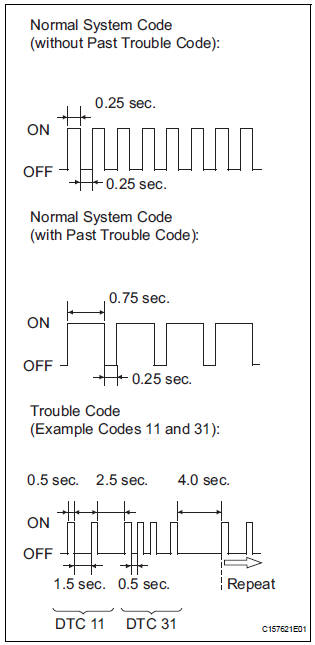
- Read the blinking patterns of the DTCs. As examples, the blinking patterns for the normal system code and trouble codes 11 and 31 are shown in the illustration.
- Normal system code indication (w/o past trouble code)
- he light blinks twice per second.
- Normal system code indication (w/ past trouble code)
- hen the past trouble code is stored in the center airbag sensor assembly, the light blinks only once per second.
- Trouble code indication
The first two blinkings indicate the first DTC.
The second blinking occurs after a 1.5- second pause.
If there are more than 1 code, there will be a 2.5- second pause between each code. After all codes are shown, there will be a 4.0-second pause, and they all will be repeated.
HINT:
- If 2 or more malfunctions are found, the indication begins with the smaller numbered code.
- If DTCs are indicated without connecting the terminals, proceed to the "Diagnosis Circuit"
2. DTC CLEAR (USING SST CHECK WIRE)
- Clear the DTCs.
- When the ignition switch is turned off, the DTCs
are cleared.
HINT: Depending on the DTC, the code may not be cleared by turning off the ignition switch. In this case, proceed to the next procedure.
- Using SST, connect terminals TC and CG of the
DLC3, and then turn the ignition switch to the
ON position.
SST 09843-18040
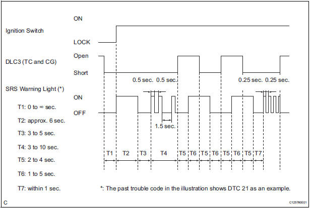
- Disconnect terminal TC of the DLC3 within 3 to 10 seconds after the DTCs are output, and check if the SRS warning light comes on after 3 seconds.
- ) Within 2 to 4 seconds after the SRS warning light comes on, connect terminals TC and CG of the DLC3.
- ) The SRS warning light should go off within 2 to 4 seconds after connecting terminals TC and CG of the DLC3. Then, disconnect terminal TC within 2 to 4 seconds after the SRS warning light goes off.
- The SRS warning light comes on again within 2
to 4 seconds after disconnecting terminal TC.
Then, reconnect terminals TC and CG of the DLC3 within 2 to 4 seconds after the SRS warning light comes on.
- Check if the SRS warning light goes off within 2
to 4 seconds after connecting terminals TC and
CG of the DLC3. Also check if the normal
system code is output within 1 second after the
SRS warning light goes off.
If DTCs are not cleared, repeat this procedure until the codes are cleared.
3. DTC CHECK
- Check the DTCs.
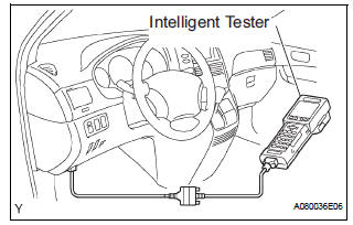
- Connect the intelligent tester to the DLC3.
- Turn the ignition switch to the ON position.
- Check the DTCs by following the prompts on the
tester screen.
HINT: Refer to the intelligent tester operator's manual for further details.
- Clear the DTCs.
- Connect the intelligent tester to the DLC3.
- Turn the ignition switch to the ON position.
- Clear the DTCs by following the prompts on the
tester screen.
HINT: Refer to the intelligent tester operator's manual for further details.
 Diagnosis system
1. CHECK DLC3
The ECU uses ISO 15765-4 for communication.
The terminal arrangement of the DLC3 complies
with SAE J1962 and matches the ISO 15765-4
format.
NOTICE:
*: Before ...
 Check mode procedure
1. CHECK MODE (SIGNAL CHECK): DTC CHECK
Connect the intelligent tester to the DLC3.
) Turn the ignition switch to the ON position.
) Select the "SIGNAL CHECK", and proceed
...
Other materials:
Removal
1. Disconnect cable from negative battery
terminal
2. REMOVE HEATED OXYGEN SENSOR (for Bank 1
Sensor 2) (See page EC-32)
3. REMOVE TAIL EXHAUST PIPE ASSEMBLY
(a) Remove the 2 bolts.
(b) Disconnect the 3 exhaust pipe supports and remove
the tail exhaust pipe assembly.
(c) Remove the gas ...
Initialization
1. RESET MEMORY
NOTICE:
Perform the RESET MEMORY (AT initialization)
when replacing the automatic transaxle assembly,
engine assembly or ECM.
The RESET MEMORY can be performed only with
the Intelligent tester.
HINT:
The ECM memorizes the condition that the ...
Taking out the jack and tools
Remove the cover.
Remove the adapter socket.
Remove the jack.
Remove the wheel nut wrench.
...