Toyota Sienna Service Manual: Removal
1. Disconnect cable from negative battery terminal
2. REMOVE HEATED OXYGEN SENSOR (for Bank 1 Sensor 2) (See page EC-32)
3. REMOVE TAIL EXHAUST PIPE ASSEMBLY
(a) Remove the 2 bolts.
(b) Disconnect the 3 exhaust pipe supports and remove the tail exhaust pipe assembly.
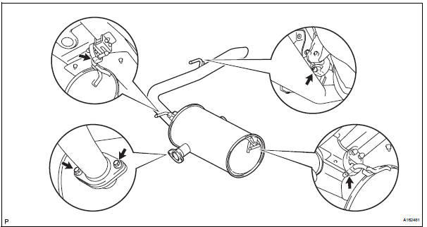
(c) Remove the gasket from the center exhaust pipe assembly.
4. REMOVE CENTER EXHAUST PIPE ASSEMBLY
(a) Remove the 2 bolts and 2 compression springs.
(b) Disconnect the 2 exhaust pipe supports and remove the center exhaust pipe assembly

(c) Remove the gasket from the front exhaust pipe assembly.
5. REMOVE FRONT EXHAUST PIPE ASSEMBLY
(a) Disconnect the heated oxygen sensor (for bank 2 sensor 2) connector.
(b) Remove the 6 nuts and front exhaust pipe assembly.

(c) Remove the 2 gaskets from the front exhaust pipe assembly.
6. REMOVE NO. 1 EXHAUST PIPE SUPPORT BRACKET

(a) Remove the bolt and No. 1 exhaust pipe support bracket.
7. REMOVE HEATED OXYGEN SENSOR (for Bank 2 Sensor 2) (See page EC-33)
 Exhaust pipe (for 2wd)
Components
...
 Installation
1. Install heated oxygen sensor (for bank 2
sensor 2) (see page ec-34)
2. Install front exhaust pipe assembly
(a) Install 2 new gaskets to the front exhaust pipe
assembly.
(b) Install the front ...
Other materials:
Folding down the third seats (manual seats)
Before folding the third seats
Fold the outside head
restraints and lower the center
head restraint to the lowest
position , and
stow the seat belt buckles.
Stow the center seat belt.
Folding down the third seatbacks
Pull the “TO FOLD/LIFT SEATBACK”
strap a
Return ...
Customer problem analysis
HINT:
In troubleshooting, confirm that the problem symptoms
have been accurately identified. Preconceptions should be
discarded in order to make an accurate judgment. To
clearly understand what the problem symptoms are, it is
extremely important to ask the customer about the
problem an ...
Adjustment
1. INSPECT SHIFT LEVER POSITION
(a) When shifting from P to R position only with ignition
switch ON and brake pedal, make sure that the
shifting lever moves smoothly and can be
moderately operated.
(b) When starting engine, make sure that the vehicle
moves forward when shifting from N to D p ...