Toyota Sienna Service Manual: ECM
COMPONENTS
REMOVAL
1. REMOVE GLOVE COMPARTMENT DOOR ASSEMBLY

(a) Push the right side wall and then push the left wall to release the stoppers.

(b) Pull the glove compartment door sub-assembly rearward to remove it.
2. REMOVE NO. 2 INSTRUMENT PANEL BOX
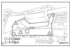
(a) Disengage the 2 claws and 4 clips, and remove the No. 2 instrument panel box.
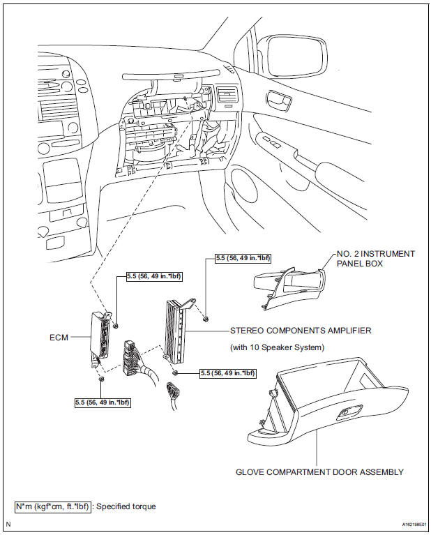
3. REMOVE ECM

(a) Disconnect the 5 ECM connectors.
(b) Remove the 2 nuts and ECM.
4. REMOVE ECM (with 10 speakers system)

(a) Disconnect the 5 ECM connectors and 2 stereo components amplifier connectors.
(b) Remove the 4 nuts and the ECM with the stereo components amplifier.
INSTALLATION

1. INSTALL ECM
(a) Install the ECM with the 2 nuts.
Torque: 5.5 N*m (56 kgf*cm, 49 in.*lbf) (b) Connect the 5 ECM connectors.
2. INSTALL ECM (with 10 speakers system)

(a) Install the ECM and stereo components amplifier with the 4 nuts.
Torque: 5.5 N*m (56 kgf*cm, 49 in.*lbf) (b) Connect the 5 ECM connectors and 2 stereo components amplifier connectors.
3.INSTALL NO. 2 INSTRUMENT PANEL BOX

(a) Install the No. 2 instrument panel box.
4. INSTALL GLOVE COMPARTMENT DOOR ASSEMBLY

(a) Install the glove compartment door sub-assembly frontward to install it.
(b) Push the right side wall and then push the left wall to install the stoppers.
5. PERFORM REGISTRATION

(a) When replacing the ECM, perform distance control ECU recognition in ECM (See page CC-125).
 Installation
1. INSTALL THROTTLE BODY
(a) Install a new throttle body gasket to the intake air
surge tank.
(b) Install the throttle body with the 4 bolts.
Torque: 10 N*m (102 kgf*cm, 7 ft.*lbf)
...
 Accelerator pedal rod
COMPONENTS
ON-VEHICLE INSPECTION
1. CHECK ACCELERATOR PEDAL ROD
(a) Check the voltage.
(1) Connect the intelligent tester to the DLC3.
(2) Turn the ignition switch to the ON position.
...
Other materials:
On-vehicle inspection
1. CHECK ACCELERATOR PEDAL ROD
Check the voltage.
Connect the intelligent tester to the DLC3.
Turn the ignition switch to the ON position.
Turn the intelligent tester on.
Select the menu items: DIAGNOSIS /
ENHANCED OBD II / DATA LIST / ALL /
ACCEL POS ...
Master Cylinder Pressure Sensor Malfunction
DTC C1246/46 Master Cylinder Pressure Sensor Malfunction
DESCRIPTION
Master cylinder pressure sensor is connected to the skid control ECU in the
actuator.
INSPECTION PROCEDURE
1 READ VALUE ON INTELLIGENT TESTER (MASTER CYLINDER PRESSURE SENSOR)
(a) Connect the intelligent tester to the DL ...
Disassembly
1. REMOVE OIL PUMP RELIEF VALVE
(A) using a 27 mm socket wrench, remove the relief
valve plug.
(B) remove the valve spring and oil pump relief valve.
2. REMOVE OIL PUMP COVER
(a) Remove the 8 bolts, oil pump cover and oil pump
rotor set. ...