Toyota Sienna Service Manual: Accelerator pedal rod
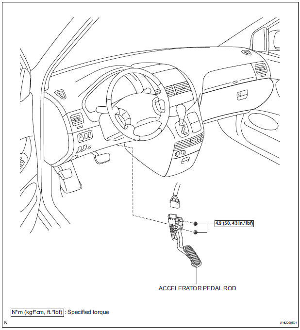
COMPONENTS
ON-VEHICLE INSPECTION
1. CHECK ACCELERATOR PEDAL ROD
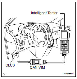
(a) Check the voltage.
(1) Connect the intelligent tester to the DLC3.
(2) Turn the ignition switch to the ON position.
(3) Turn the intelligent tester on.
(4) Select the menu items: DIAGNOSIS / ENHANCED OBD II / DATA LIST / ALL / ACCEL POS #1, ACCEL POS #2.
(5) Operate the accelerator pedal, and then check that the ACCEL POS #1 and ACCEL POS #2 values are within the specifications.
Standard voltage (ACCEL POS #1)

If the result is not as specified, check the accelerator pedal rod, wire harness or ECM.
REMOVAL
1. REMOVE ACCELERATOR PEDAL ROD
(a) Disconnect the accelerator pedal position sensor connector.
(b) Remove the 2 nuts and accelerator pedal rod.
INSTALLATION
1. INSTALL ACCELERATOR PEDAL ROD

NOTICE:
|
(a) Install the accelerator pedal rod with the 2 nuts.
Torque: 4.9 N*m (50 kgf*cm, 43 in.*lbf) (b) Connect the accelerator pedal position sensor connector.
 ECM
ECM
COMPONENTS
REMOVAL
1. REMOVE GLOVE COMPARTMENT DOOR ASSEMBLY
(a) Push the right side wall and then push the left wall
to release the stoppers.
(b) Pull the glove compartment door sub-as ...
 Mass air flow meter
COMPONENTS
ON-VEHICLE INSPECTION
1. INSPECT MASS AIR FLOW METER
NOTICE:
Perform the mass air flow (MAF) meter inspection
by following the procedures below.
Only replace t ...
Other materials:
Diagnosis Circuit
DESCRIPTION
DTC output mode is set by connecting terminals TC and CG of the DLC3.
DTCs are displayed by blinking the SRS warning light.
HINT:
When each warning light stays blinking, a ground short in the
wiring of terminal TC of the DLC3 or an
internal ground short in each ECU is ...
ON / OFF Indication Parameter Error
DTC 01-E2 ON / OFF Indication Parameter Error
DESCRIPTION
DTC No.
DTC Detection Condition
Trouble Area
01-E2
The command for ON/OFF control from the master
device has a problem.
Radio receiver
INSPECTION PROCEDURE
HINT:
After the inspection is ...
Anti-glare function
Manual anti-glare inside rear view mirror
Reflected light from the headlights of vehicles behind can be reduced
by operating the lever.
Normal position
Anti-glare position
Auto anti-glare inside rear view mirror
Responding to the level of brightness of the headlights of veh ...