Toyota Sienna Service Manual: Engine rear oil seal
Components

Removal
1. REMOVE AUTOMATIC TRANSAXLE ASSEMBLY (for 2WD)
HINT:
See page AX-163.
2. REMOVE AUTOMATIC TRANSAXLE ASSEMBLY (for 4WD)
HINT: See page AX-167.
3. REMOVE DRIVE PLATE AND RING GEAR SUBASSEMBLY

(a) Using SST, hold the crankshaft.
SST 09213-70011 (09213-70020), 09330-00021

(b) Remove the 8 bolts, front spacer, drive plate and rear spacer.
4. REMOVE ENGINE REAR OIL SEAL

(a) Using a knife, cut off the oil seal lip.
(b) Using a screwdriver, pry out the oil seal.
NOTICE:
Be careful not to damage the crankshaft. Tape the screwdriver tip before use.
INSTALLATION
1. INSTALL ENGINE REAR OIL SEAL
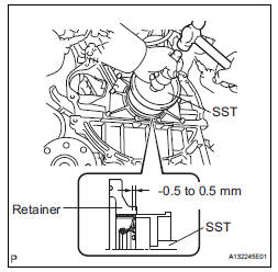
(a) Apply MP grease to a new oil seal lip.
(b) Using SST and a hammer, tap in the oil seal.
SST 09223-15030, 09950-70010 (09951-07150) Oil seal tap in depth: -0.5 to 0.5 mm (-0.020 to 0.020 in.)
2. INSTALL DRIVE PLATE AND RING GEAR SUBASSEMBLY

(a) Using SST, hold the crankshaft.
SST 09213-70011 (09213-70020), 09330-00021

(b) Apply adhesive to 2 or 3 threads of the mounting bolt end.
Adhesive: Part No. 08833-00070, THREE BOND 1324 or equivalent
(1) Install the front spacer, drive plate and rear spacer on the crankshaft.
(2) Install and tighten the 8 mounting bolts uniformly in several steps.
Torque: 83 N*m (850 kgf*cm, 61 ft.*lbf)

3. INSTALL AUTOMATIC TRANSAXLE ASSEMBLY (for 2WD)
HINT:
See page AX-166.
4. INSTALL AUTOMATIC TRANSAXLE ASSEMBLY (for 4WD)
HINT:
See page AX-167.
 Engine front oil seal
COMPONENTS
REMOVAL
1. REMOVE FRONT WHEEL RH
2. REMOVE FRONT FENDER APRON SEAL RH (See
page EM-26)
3. REMOVE V-RIBBED BELT (See page EM-6)
4. REMOVE CRANKSHAFT PULLEY
(a) Using SST, loos ...
 Engine assembly
Components
REMOVAL
1. DISCHARGE FUEL SYSTEM PRESSURE (See page
FU-13)
2. DISCHARGE REFRIGERANT FROM
REFRIGERATION SYSTEM (See page AC-172)
3. REMO ...
Other materials:
Removal
1. REMOVE ENGINE ASSEMBLY WITH TRANSAXLE
HINT:
(See page EM-26)
2. REMOVE FRONT DRIVE SHAFT ASSEMBLY LH
HINT:
(See page DS-6)
3. REMOVE FRONT DRIVE SHAFT ASSEMBLY RH
HINT:
(See page DS-6)
4. REMOVE TRANSMISSION CONTROL CABLE CLAMP
(a) Remove the bolt and the transmission control cable
cla ...
Horn
To sound the horn, press on or
close to the mark.
WARNINGCaution while driving
Do not adjust the steering wheel while driving.
Doing so may cause the driver to mishandle the vehicle and cause an
accident,
resulting in death or serious injury.
After adjusting the steeri ...
Audio system operation buttons
“AUDIO” button
Display the “Select Audio Source” screen or audio top screen.
“SETUP” button
Press this button to customize the function settings.
“CAR” button
Press this button to access the vehicle information.
button
Press this button to access the Blue ...