Toyota Sienna Service Manual: Evaporative Emission Control System Leak Detected

DTC SUMMARY
DESCRIPTION
The circuit description can be found in the EVAP (Evaporative Emission) System (See page ES-409).
INSPECTION PROCEDURE
Refer to the EVAP System (See page ES-412).
MONITOR DESCRIPTION
5 hours*1 after the ignition switch is turned off, the electric vacuum pump creates negative pressure (vacuum) in the EVAP (Evaporative Emission) system. The ECM monitors for leaks and actuator malfunctions based on the EVAP pressure.
HINT:
*1: If the engine coolant temperature is not below 35°C (95°F) 5 hours after the ignition switch is turned off, the monitor check starts 2 hours later. If it is still not below 35°C (95°F) 7 hours after the ignition switch is turned off, the monitor check starts 2.5 hours later.


*2: If only a small amount of fuel is in the fuel tank, it takes longer for the EVAP pressure to stabilize.

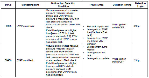
1. P0455: EVAP (Evaporative Emission) gross leak
In operation C, the vacuum pump creates negative pressure (vacuum) in the EVAP system and the EVAP system pressure is measured. If the stabilized system pressure is higher than [second 0.02 inch leak pressure standard x 0.2] (near atmospheric pressure), the ECM determines that the EVAP system has a large leak, illuminates the MIL and sets the DTC (2 trip detection logic).
2. P0456: EVAP very small leak
In operation C, the vacuum pump creates negative pressure (vacuum) in the EVAP system and the EVAP system pressure is measured. If the stabilized system pressure is higher than second 0.02 inch leak pressure standard, the ECM determines that the EVAP system has a small leak, illuminates the MIL and sets the DTC (2 trip detection logic).

MONITOR STRATEGY

TYPICAL ENABLING CONDITIONS


Key-off monitor sequence 1 to 8

TYPICAL MALFUNCTION THRESHOLDS

MONITOR RESULT
Refer to CHECKING MONITOR STATUS (See page ES-19).
 Evaporative Emission Control System Incorrect Purge Flow
DTC SUMMARY
DESCRIPTION
The circuit description can be found in the EVAP (Evaporative Emission)
System (See page ES-409).
INSPECTION PROCEDURE
Refer to the EVAP System (See page ES-412).
MO ...
 Vehicle Speed Sensor "A"
DESCRIPTION
The speed sensor detects the wheel speed and sends the appropriate signals to
the skid control ECU.
The skid control ECU converts these wheel speed signals into a 4-pulse signal ...
Other materials:
Back door lock
INSPECTION
1. INSPECT BACK DOOR LOCK ASSEMBLY (W/O
CLOSER)
Check operation of the door lock.
Using a screwdriver, push the latch in order to
put the back door lock in the locked condition
(full-latch position).
Connect the battery positive (+) lead to terminal ...
Clearance warning ECU
COMPONENTS
REMOVAL
1. REMOVE FRONT DOOR SCUFF PLATE LH
2. REMOVE COWL SIDE TRIM BOARD LH
3. REMOVE INSTRUMENT PANEL FINISH PANEL SUBASSEMBLY LOWER LH
4. REMOVE NO. 1 INSTRUMENT PANEL SAFETY PAD INSERT SUB-ASSEMBLY
5. REMOVE CLEARANCE WARNING ECU
Disconnect each connector.
&nb ...
Reassembly
1. INSTALL PLANETARY GEAR
(a) Apply grease to the planetary gears and pin parts of
the planetary shaft.
(b) Install the 3 planetary gears.
2. INSTALL STARTER ARMATURE ASSEMBLY
(a) Apply grease to the plate washer and the armature
shaft.
(b) Install the starter armature to the star ...