Toyota Sienna Service Manual: Front Occupant Classification Sensor RH Circuit Malfunction
DTC B1781 Front Occupant Classification Sensor RH Circuit Malfunction
DESCRIPTION
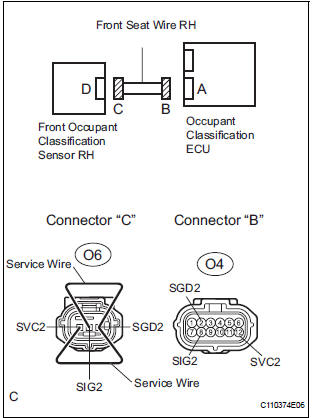
The front occupant classification sensor RH circuit consists of the occupant classification ECU and the front occupant classification sensor RH.
DTC B1781 is recorded when a malfunction is detected in the front occupant classification sensor RH circuit.
|
DTC No. |
DTC Detecting Condition |
Trouble Area |
|
B1781 |
|
|
WIRING DIAGRAM

INSPECTION PROCEDURE
HINT:
- If troubleshooting (wire harness inspection) is difficult to perform, remove the front passenger seat installation bolts to see the under surface of the seat cushion.
- In the above case, hold the seat so that it does not fall down. Holding the seat for a long period of time may cause a problem, such as seat rail deformation. Hold the seat only as necessary.
1 CHECK DTC
- Turn the ignition switch to the ON position.
- Clear the DTCs stored in the memory.
HINT: First clear DTCs stored in the occupant classification ECU and then in the center airbag sensor assembly.
- Turn the ignition switch to the LOCK position.
- Turn the ignition switch to the ON position.
- Check the DTCs (35).
OK: DTC B1781 is not output. HINT: Codes other than DTC B1781 may be output at this time, but they are not related to this check.
 USE SIMULATION METHOD TO CHECK

2 CHECK CONNECTION OF CONNECTORS
- Turn the ignition switch to the LOCK position.
- Disconnect the negative (-) terminal cable from the battery, and wait for at least 90 seconds.
- Check that the connectors are properly connected to the occupant classification ECU and the front occupant classification sensor RH.
OK: The connectors are properly connected.
 CONNECT CONNECTORS, THEN GO
TO
STEP 1
CONNECT CONNECTORS, THEN GO
TO
STEP 1

3 CHECK FRONT SEAT WIRE RH (SHORT TO B+)

- Disconnect the connectors from the occupant classification ECU and the front occupant classification sensor RH.
- Connect the negative (-) terminal cable to the battery.
- Turn the ignition switch to the ON position.
- Measure the voltage according to the value(s) in the table below.
Standard voltage

 REPAIR OR REPLACE FRONT SEAT
WIRE
RH
REPAIR OR REPLACE FRONT SEAT
WIRE
RH

4 CHECK FRONT SEAT WIRE RH (OPEN)
- Turn the ignition switch to the LOCK position.
- Disconnect the negative (-) terminal cable from the battery, and wait for at least 90 seconds.
- Using a service wire, connect O6-1 (SVC2) and O6-3
(SGD2), and connect O6-2 (SIG2) and O6-3 (SGD2) of
connector "C".
NOTICE: Do not forcibly insert a service wire into the terminals of the connector when connecting.
- Measure the resistance according to the value(s) in the table below.
Standard resistance

 REPAIR OR REPLACE FRONT SEAT
WIRE
RH
REPAIR OR REPLACE FRONT SEAT
WIRE
RH

5 CHECK FRONT SEAT WIRE RH (SHORT)

- Disconnect the service wire from connector "C".
- Measure the resistance according to the value(s) in the table below.
Standard resistance

 REPAIR OR REPLACE FRONT SEAT
WIRE
RH
REPAIR OR REPLACE FRONT SEAT
WIRE
RH

6 CHECK FRONT SEAT WIRE RH (SHORT TO GROUND)

- Measure the resistance according to the value(s) in the table below.
Standard resistance

 REPAIR OR REPLACE FRONT SEAT
WIRE
RH
REPAIR OR REPLACE FRONT SEAT
WIRE
RH

7 CHECK DTC
- Connect the connectors to the occupant classification ECU and the front occupant classification sensor RH.
- Connect the negative (-) terminal cable to the battery.
- Turn the ignition switch to the ON position.
- Clear the DTCs stored in the memory.
HINT: First clear DTCs stored in the occupant classification ECU and then in the center airbag sensor assembly.
- Turn the ignition switch to the LOCK position.
- Turn the ignition switch to the ON position.
- Check the DTCs (35).
OK: DTC B1781 is not output. HINT: Codes other than DTC B1781 may be output at this time, but they are not related to this check.
 USE SIMULATION METHOD TO CHECK

8 REPLACE OCCUPANT CLASSIFICATION ECU
- Turn the ignition switch to the LOCK position.
- Disconnect the negative (-) terminal cable from the battery, and wait for at least 90 seconds.
- Replace the occupant classification ECU.
HINT: Perform the inspection using parts from a normal vehicle if possible

9 PERFORM ZERO POINT CALIBRATION
- Connect the negative (-) terminal cable to the battery.
- Connect the intelligent tester to the DLC3.
- Turn the ignition switch to the ON position.
- Using the intelligent tester, perform "Zero point calibration" (28).
OK: "COMPLETED" is displayed
 Go to step 12

10 PERFORM SENSITIVITY CHECK
- Using the intelligent tester, perform "Sensitivity check" (28).
Standard value: 27 to 33 kg (59.52 to 72.75 lb)
 Go to step 12

11 CHECK DTC
- Turn the ignition switch to the ON position.
- Clear the DTCs stored in the memory.
HINT: First clear DTCs stored in the occupant classification ECU and then in the center airbag sensor assembly.
- Turn the ignition switch to the LOCK position.
- Turn the ignition switch to the ON position.
- Check the DTCs (35).
OK: DTC B1781 is not output. HINT: Codes other than DTC B1781 may be output at this time, but they are not related to this check
 END
END

12 REPLACE FRONT SEAT ASSEMBLY RH
- Turn the ignition switch to the LOCK position.
- Disconnect the negative (-) terminal cable from the battery, and wait for at least 90 seconds.
- Replace the front seat assembly RH ( for flat type, SE-48 for manual seat, SE-58 for power seat).

13 PERFORM ZERO POINT CALIBRATION
- Connect the negative (-) terminal cable to the battery.
- Connect the intelligent tester to the DLC3.
- Turn the ignition switch to the ON position.
- Using the intelligent tester, perform "Zero point calibration" (28).
OK: "COMPLETED" is displayed.

14 PERFORM SENSITIVITY CHECK
- Using the intelligent tester, perform "Sensitivity check" (28).
Standard value: 27 to 33 kg (59.52 to 72.75 lb)

END
 Front Occupant Classification Sensor LH Circuit
Malfunction
Front Occupant Classification Sensor LH Circuit
Malfunction
DTC B1780 Front Occupant Classification Sensor LH Circuit
Malfunction
DESCRIPTION
The front occupant classification sensor LH circuit consists of the occupant
classification ECU and the
front oc ...
 Rear Occupant Classification Sensor LH Circuit
Malfunction
Rear Occupant Classification Sensor LH Circuit
Malfunction
DTC B1782 Rear Occupant Classification Sensor LH Circuit
Malfunction
DESCRIPTION
The rear occupant classification sensor LH circuit consists of the occupant
classification ECU and the rear
occup ...
Other materials:
Safety Connect
Safety Connect is a subscription-based telematics service that
uses Global Positioning System (GPS) data and embedded cellular
technology to provide safety and security features to subscribers.
Safety Connect is supported by Toyota’s designated
response center, which operates 24 hours per da ...
Short to GND in Curtain Shield Squib LH Circuit
DTC B1167/85 Short to GND in Curtain Shield Squib LH Circuit
DESCRIPTION
The curtain shield squib LH circuit consists of the center airbag sensor
assembly and the curtain shield
airbag assembly LH.
The circuit instructs the SRS to deploy when deployment conditions are met.
DTC B1167/85 is ...
Reassembly
1. INSTALL BRAKE MASTER LESS RESERVOIR TANK CYLINDER SUB-ASSEMBLY
(a) Apply lithium soap base glycol grease to the 2 brake
master cylinder union grommets and install them to
the brake master less reservoir tank cylinder subassembly.
(b) Using a pin punch (φ 5 mm) and hammer, install the
...