Toyota Sienna Service Manual: Headlight dimmer switch
COMPONENTS
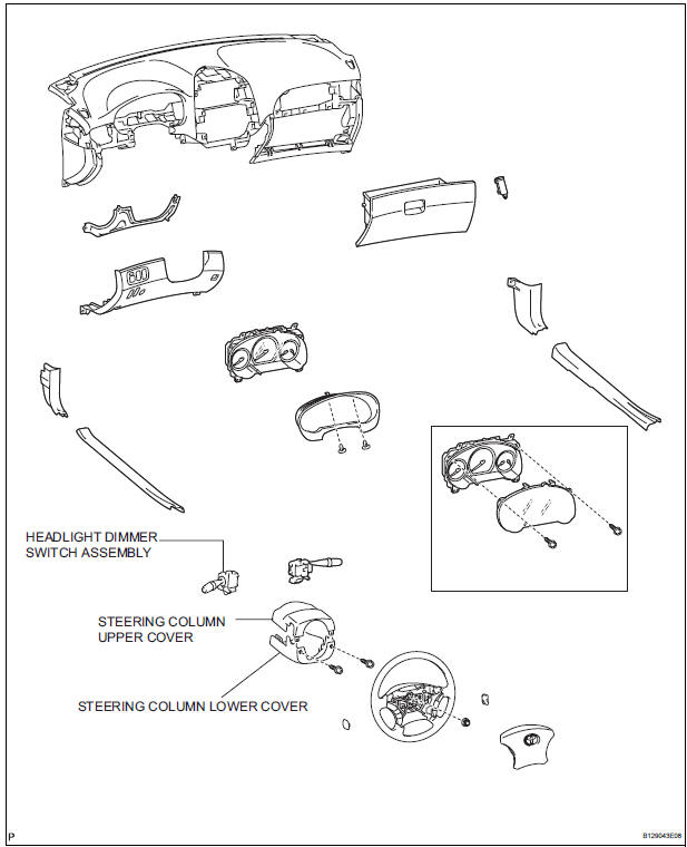
REMOVAL
1. REMOVE STEERING COLUMN LOWER COVER
2. REMOVE STEERING COLUMN UPPER COVER
3. REMOVE HEADLIGHT DIMMER SWITCH ASSEMBLY

- Disconnect the connector.
- Release the claw fitting and remove the headlight dimmer switch assembly.
INSPECTION
1. HEADLIGHT DIMMER SWITCH ASSEMBLY

- Inspect light control switch resistance.
- Check that there is resistance between the terminals at each switch position as shown in the chart.
Resistance
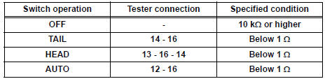
- Inspect light control switch resistance.
- Check that there is resistance between the terminals at each switch position as shown in the chart.
Resistance

- Inspect light control switch resistance.
- Check that there is resistance between the terminals at each switch position as shown in the chart.
Resistance

- Inspect light control switch resistance.
- Check that there is resistance between the terminals at each switch position as shown in the chart.
Resistance

INSTALLATION
1. INSTALL HEADLIGHT DIMMER SWITCH ASSEMBLY
2. INSTALL STEERING COLUMN UPPER COVER
3. INSTALL STEERING COLUMN LOWER COVER
 Vanity light
ON-VEHICLE INSPECTION
1. LH VISOR ASSEMBLY
Inspect vanity light resistance.
check that the resistance exists between the
terminal 1 and the terminal 2 when the light is
oper ...
 Turn signal light switch
ON-VEHICLE INSPECTION
1. INSPECT TURN SIGNAL FLASHER CIRCUIT
Measure voltage between the terminals as shown in
the chart below.
Voltage
Connect the connector to turn the si ...
Other materials:
Removal
1. REMOVE ENGINE ASSEMBLY WITH TRANSAXLE
HINT:
(See page EM-34)
2. REMOVE TRANSVERSE ENGINE ENGINE MOUNTING INSULATOR
(a) Remove the 3 nuts and transverse engine engine
mounting insulator.
3. REMOVE FRONT SUSPENSION ARM SUBASSEMBLY LOWER NO.1 LH
(a) Remove the 2 bolts on the front sid ...
Short in Curtain Shield Squib RH Circuit
DTC B1160/83 Short in Curtain Shield Squib RH Circuit
DESCRIPTION
The curtain shield squib RH circuit consists of the center airbag sensor
assembly and the curtain shield
airbag assembly RH.
The circuit instructs the SRS to deploy when deployment conditions are met.
DTC B1160/83 is record ...
Front floor footrest
COMPONENTS
Removal
1. REMOVE FRONT FLOOR FOOTREST
Using a screwdriver, disengage the 2 clips and
remove the footrest.
HINT:
Tape the screwdriver tip before use.
Disengage the clips and then remove the 2 clips
from the footrest.
INSTALLATION
1. INSTALL FRONT FLOOR FOOTREST ...