Toyota Sienna Service Manual: Illumination Circuit
DESCRIPTION
Power is supplied to the radio receiver and steering pad switch illumination when the light control switch is in the TAIL or HEAD position.
WIRING DIAGRAM

INSPECTION PROCEDURE
NOTICE: The vehicle is equipped with an SRS (Supplemental Restraint System) which includes components such as airbags. Before servicing (including removal or installation of parts), be sure to read the precautionary notice for the supplemental restraint system
1 CHECK ILLUMINATION
- Check if the illumination for the radio receiver, steering pad switch, glove box or others (hazard switch, cigarette lighter, etc.) comes on when the light control switch is turned to the HEAD or TAIL position.
Result

2 CHECK HARNESS AND CONNECTOR (BATTERY - SPIRAL CABLE)

- Disconnect the spiral cable connector.
- Measure the voltage according to the value(s) in the table below.
Standard voltage

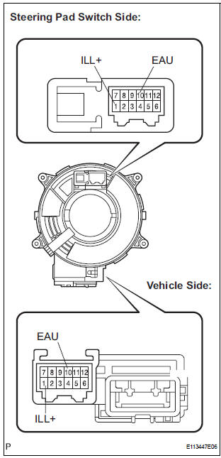
3 INSPECT STEERING PAD SWITCH ASSEMBLY
- Disconnect the steering pad switch connector.
- Connect the positive (+) lead to terminal ILL+ and the negative (-) lead to terminal EAU of the steering pad switch assembly connector.

- Check if the illumination for the steering pad switch assembly comes on.
OK: Illumination for the steering pad switch assembly comes on.
4 INSPECT SPIRAL CABLE
- Disconnect the steering pad switch and and spiral cable connectors.
- Measure the resistance according to the value(s) in the table below.
Standard resistance

NOTICE: The spiral cable is an important part of the SRS airbag system. Incorrect removal or installation of the spiral cable may prevent the airbag from deploying. Be sure to read the page shown in the brackets
5 CHECK HARNESS AND CONNECTOR (SPIRAL CABLE - RADIO RECEIVER)

- Disconnect the connectors from the radio receiver and spiral cable.
- Measure the resistance according to the value(s) in the table below.
Standard resistance

*1: 10 Speaker without Navigation System
*2: 6 Speaker with Rear Seat Entertainment System
*3: 6 Speaker without Rear Seat Entertainment System
PROCEED TO NEXT CIRCUIT INSPECTION SHOWN IN PROBLEM SYMPTOMS TABLE
6 CHECK HARNESS AND CONNECTOR (BATTERY - RADIO RECEIVER)

- Disconnect the radio receiver connector.
- Measure the voltage according to the value(s) in the table below.
Standard voltage

*1: 10 Speaker without Navigation System
*2: 6 Speaker with Rear Seat Entertainment System
*3: 6 Speaker without Rear Seat Entertainment System
7 CHECK HARNESS AND CONNECTOR (RADIO RECEIVER - COMBINATION METER)

- Disconnect the radio receiver connector and combination meter connector.
- Measure the resistance according to the value(s) in the table below.
Standard resistance

*1: 10 Speaker without Navigation System
*2: 6 Speaker with Rear Seat Entertainment System
*3: 6 Speaker without Rear Seat Entertainment System
PROCEED TO NEXT CIRCUIT INSPECTION SHOWN IN PROBLEM SYMPTOMS TABLE
 Steering Pad Switch Circuit
DESCRIPTION
This circuit sends an operation signal from the steering pad switch to the
radio receiver.
If there is an open in the circuit, the audio system cannot be operated using
the steerin ...
 Speaker Circuit
DESCRIPTION
When the vehicle has a built-in type amplifier, a sound signal is
sent from the radio receiver to the
speakers via the "6 Speaker System" circuit.
When the ...
Other materials:
DVD-ROM Abnormal
DVD-ROM Abnormal
DESCRIPTION
DTC No.
DTC Detection Condition
Trouble Area
44-43
DVD-ROM operation is abnormal.
DVD
Television display assembly
INSPECTION PROCEDURE
HINT:
After the inspection is completed, clear the DTCs ...
Installation
1. INSTALL BRAKE VACUUM CHECK VALVE
ASSEMBLY
(a) Install the brake vacuum check valve assembly and
check valve grommet to the brake booster
assembly.
2. INSTALL BRAKE BOOSTER GASKET
(a) Install a new brake booster gasket to the brake
booster with master cylinder.
3. INSTALL BRAKE MASTER CYLI ...
Disc cannot be Played/ No Playable Files/ Copyright Protection Error/ Disc
cannot be Played/ No Playable Files/ Copyright Protection Error
DTC 62-7D Disc cannot be Played
DTC 62-7E No Playable Files
DTC 62-7F Copyright Protection Error
DTC 63-7D Disc cannot be Played
DTC 63-7E No Playable Files
DTC 63-7F Copyright Protection Error
DESCRIPTION
INSPECTION PROCEDURE
HINT:
After the inspection is completed, clear the DTCs.
1 ...