Toyota Sienna Service Manual: Speaker Circuit
DESCRIPTION
- When the vehicle has a built-in type amplifier, a sound signal is sent from the radio receiver to the speakers via the "6 Speaker System" circuit.
- When the vehicle has a separate type amplifier, a sound signal from the radio receiver is amplified by the stereo component amplifier and then transmitted to the speaker via the "10 Speaker System" circuit.
If there is a short in this circuit, the stereo component amplifier detects it and stops output to the speakers.
Thus sound cannot be heard from the speakers even if there is no malfunction in the stereo component amplifier or speakers
WIRING DIAGRAM


1 CHECK HARNESS AND CONNECTOR

- Disconnect the connectors shown in the illustration from the stereo component amplifier or radio receiver and speakers.
- 10 Speaker System:
Measure the resistance between each of the front No. 2
speakers and the stereo component amplifier to check
for an open circuit in the wire harness.
Standard resistance: Below 1 Ω
- 6 speaker System:
Measure the resistance between each of the front No. 2
speakers and the radio receiver to check for an open
circuit in the wire harness.
Standard resistance: Below 1 Ω
- Measure the resistance between each of the front No. 2
speakers and each of the front No. 1 speakers to check
for an open circuit in the wire harness.
Standard resistance: Below 1 Ω
- 10 Speaker System:
Measure the resistance between each of the rear
speakers and the stereo component amplifier to check
for an open circuit in the wire harness.
Standard resistance: Below 1 Ω
- 6 Speaker System:
Measure the resistance between each of the rear
speakers and the radio receiver to check for an open
circuit in the wire harness.
Standard resistance: Below 1 Ω
- 10 Speaker System:
Measure the resistance between each of the rear stereo
component speakers and the stereo component
amplifier to check for an open circuit in the wire harness.
Standard resistance: Below 1 Ω
- 10 Speaker System:
Measure the resistance between the front stereo
component speaker and the stereo component amplifier
to check for an open circuit in the wire harness.
Standard resistance: Below 1 Ω

- 10 Speaker System:
Measure the resistance between the woofer box speaker
and the stereo component amplifier to check for an open
circuit in the wire harness.
Standard resistance: Below 1 Ω
- Measure the resistance between the each speaker and
body ground to check for a short circuit in the wire
harness.
Standard resistance: 10 kΩ or higher
2 INSPECT FRONT NO. 1 SPEAKER
- Resistance check.
- Measure the resistance between the terminals of
the speaker.
Standard resistance: 10 Speaker System: 4 to 6 Ω
6 Speaker System: Approximately 4 Ω
3 INSPECT REAR SPEAKER
- Resistance check.
- Measure the resistance between the terminals of
the speaker.
10 Speaker System: Approximately 2.4 Ω
6 Speaker System: Approximately 4 Ω
4 INSPECT FRONT NO. 2 SPEAKER
- Check that the malfunction disappears when another
speaker in good condition is installed.
Standard: Malfunction disappears.
HINT:
- Connect all the connectors to the front No. 2 speaker.
- When there is a possibility that either the right or left front speaker is detective, inspect by interchanging the right one with the left one.
- Perform the above inspection on both LH and RH sides.
5 CONFIRM MODEL
Result

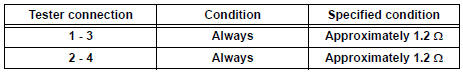
6 INSPECT WOOFER BOX SPEAKER

- Resistance check.
- Measure the resistance according to the value(s) in the table below.
NOTICE: The speaker should not be removed for checking.
Standard resistance
7 INSPECT REAR STEREO COMPONENT SPEAKER
- Check that the malfunction disappears when another speaker in good condition is installed.
OK: Malfunction disappears.
HINT:
- Connect all the connectors to the rear stereo component speaker.
- When there is a possibility that either the right or left rear speaker is detective, inspect by interchanging the right one with the left one
8 INSPECT FRONT STEREO COMPONENT SPEAKER
- Resistance check.
- Measure the resistance between the terminals of
the speaker.
Standard resistance: 1.2 to 2.2 Ω
PROCEED TO NEXT CIRCUIT INSPECTION SHOWN IN PROBLEM SYMPTOMS TABLE
 Illumination Circuit
DESCRIPTION
Power is supplied to the radio receiver and steering pad switch illumination
when the light control switch is
in the TAIL or HEAD position.
WIRING DIAGRAM
INSPECTION PROCEDURE
N ...
 Sound Signal Circuit between Radio Receiver and Stereo Component
Amplifier
Sound Signal Circuit between Radio Receiver and Stereo Component
Amplifier
DESCRIPTION
The radio receiver sends a sound signal to the stereo component amplifier
through this circuit.
The sound signal that has been sent is amplified by the stereo component
amplifier, ...
Other materials:
AUX Port/USB Port
Connect an iPod, USB memory device or portable audio player
to the AUX port/USB port as indicated below. Select “iPod”,
“USB” or “AUX” on the audio source selection screen and the
device can be operated via audio system.
Connecting using the AUX port/USB port
iPod
Open the cove ...
Checking monitor status
The purpose of the monitor result (mode 06) is to allow
access to the results for on-board diagnostic monitoring tests
of specific components/systems that are not continuously
monitored. Examples are catalyst, evaporative emission
(EVAP) and thermostat.
The monitor result allows the OBD II sc ...
Installation
1. INSTALL STEERING PAD
Support the steering pad with one hand as shown in
the illustration.
Connect the 2 connectors to the steering pad.
NOTICE:
When handling the airbag connector, take care
not to damage the airbag wire harness.
Connect the horn connector.
...