Toyota Sienna Service Manual: Initialization
1. ZERO POINT CALIBRATION
NOTICE: Make sure that the front passenger seat is not occupied before performing the operation.
HINT: Perform the zero point calibration and sensitivity check if any of the following conditions occur.
- The occupant classification ECU is replaced.
- Accessories (seatback tray and seat cover, etc.) are installed.
- The front passenger seat is removed from the vehicle.
- The passenger airbag ON/OFF indicator ("OFF") comes on when the front passenger seat is not occupied.
- The vehicle is brought to the workshop for repair due to an accident or a collision.
- Zero point calibration and sensitivity check procedures
HINT: Make sure that zero point calibration has finished normally, and then perform the sensitivity check.
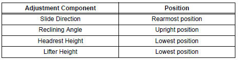
- Adjust the seat position according to the table below.
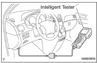
- Connect the intelligent tester to the DLC3.
- Turn the ignition switch to the ON position.
- Perform the zero point calibration by following the prompts on the tester screen.
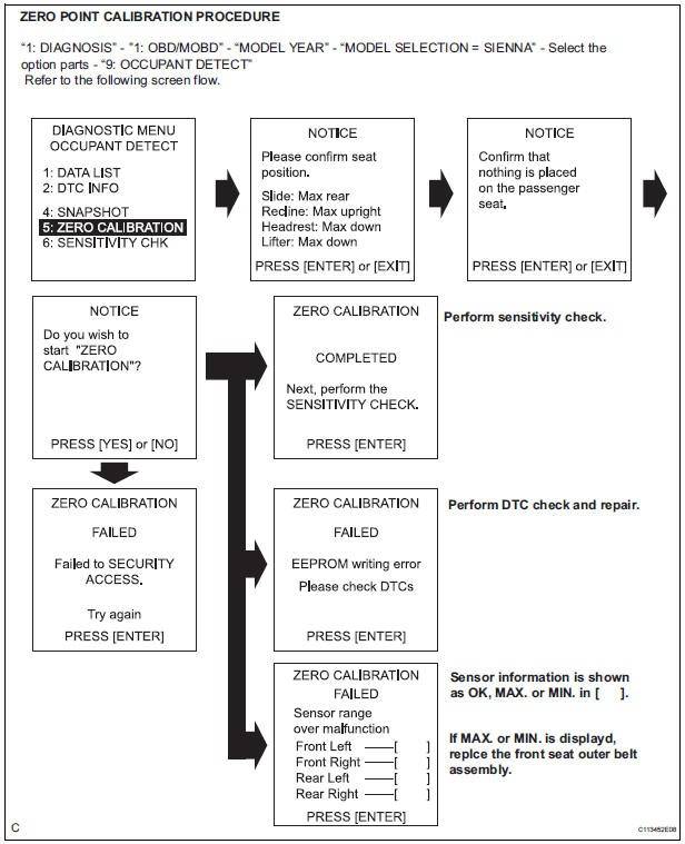
HINT: Refer to the intelligent tester operator's manual for further details.
OK: "COMPLETE" is displayed.
- Perform the sensitivity check by following the prompts on the tester screen.
- Confirm that the beginning sensor reading is
within the standard range.
Standard value: -3.2 to 3.2 kg (-7 to 7 lb)
- Place a 30 kg (66.14 lb) weight (eg. a 30 kg (66.14 lb) of lead mass) onto the front passenger seat.
- Confirm that the sensitivity is within the standard range.
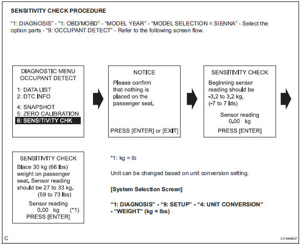
Standard value: 27 to 33 kg (59.52 to 72.75 lb)
HINT:
- When performing the sensitivity check, use a solid metal weight (the check result may not appear properly if a liquid weight is used).
- If the sensitivity deviates from the standard range, retighten the bolts of the front passenger seat taking care not to deform the seat rail. After performing this procedure, if the sensitivity is not within the standard range, replace the front seat assembly RH.
- If zero point calibration has not finished normally, replace the front seat assembly RH.
 How to proceed with
troubleshooting
How to proceed with
troubleshooting
The intelligent tester can be used in steps 4, 6, 8 and 9.
1 VEHICLE BROUGHT TO WORKSHOP
2 CUSTOMER PROBLEM ANALYSIS
3 PASSENGER AIRBAG ON/OFF INDICATOR CHECK
4 DTCs CHECK (Present and Past DTCs)
...
 Problem symptoms table
HINT:
Proceed to the troubleshooting for each circuit in the table
below.
Occupant Classification System
Symptom
Suspected area
The front passenger seat condition differ ...
Other materials:
Control Module Performance
DESCRIPTION
The ECM continuously monitors its main and sub CPUs. This self-check ensures
that the ECM is
functioning properly. If outputs from the CPUs are different and deviate from
the standards, the ECM will
illuminate the MIL and set a DTC immediately.
The ECM also monitors the cru ...
How to proceed with
troubleshooting
HINT:
*: Use the intelligent tester.
1 VEHICLE BROUGHT TO WORKSHOP
2 CUSTOMER PROBLEM ANALYSIS
Confirm problem symptoms
3 CHECK MULTIPLEX COMMUNICATION SYSTEM*
Check if the multiplex communication system DTC is
output.
HINT:
The center airbag sensor assembly of this system is
co ...
Short in Curtain Shield Squib RH Circuit
DTC B1160/83 Short in Curtain Shield Squib RH Circuit
DESCRIPTION
The curtain shield squib RH circuit consists of the center airbag sensor
assembly and the curtain shield
airbag assembly RH.
The circuit instructs the SRS to deploy when deployment conditions are met.
DTC B1160/83 is record ...