Toyota Sienna Service Manual: Installation
1. INSTALL RACK & PINION POWER STEERING GEAR ASSEMBLY

(a) Install the power steering gear assembly with the 2 bolts and nuts.
Torque: 70 N*m (714 kgf*cm, 52 ft.*lbf)
2. CONNECT PRESSURE FEED TUBE ASSEMBLY

(a) Connect the pressure feed tube assembly to the power steering gear assembly.
(b) Install the clip.
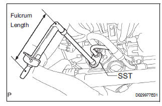
(c) Using SST, connect the return tube assembly to the power steering gear assembly.
SST 09023-12701 Torque: 22.5 N*m (229 kgf*cm, 17 ft.*lbf)
HINT
- Use a torque wrench with a fulcrum length of 300 mm (11.81 in.).
- This torque value is effective when SST is parallel to the torque wrench.

(d) Install the tube clamp with the bolt.
Torque: 9.8 N*m (100 kgf*cm, 87 in.*lbf)

(e) Install the tube clamp with the nut.
Torque: 9.8 N*m (100 kgf*cm, 87 in.*lbf)
3. INSTALL FRONT STABILIZER BRACKET NO.1 LH

(a) Install the stabilizer bracket No. 1 with the 2 bolts.
Torque: 17 N*m (173 kgf*cm, 12 ft.*lbf)
4. INSTALL FRONT STABILIZER BRACKET NO.1 RH
HINT: Perform the same procedure on the other side.
5. INSTALL FRONT STABILIZER LINK ASSEMBLY LH
6. INSTALL FRONT STABILIZER LINK ASSEMBLY RH
HINT: Perform the same procedure on the other side.
7. INSTALL STEERING INTERMEDIATE SHAFT ASSEMBLY

(a) Align matchmarks on the intermediate shaft assembly and power steering gear assembly.
(b) Install the bolt.
Torque: 36 N*m (367 kgf*cm, 27 ft.*lbf)

(c) Install the dust cover.
HINT: Ensure that the springs are installed tightly.
8. INSTALL TIE ROD ASSEMBLY LH
9. INSTALL TIE ROD ASSEMBLY RH
HINT: Perform the same procedure on the other side.
10. INSTALL FRONT WHEEL Torque: 103 N*m (1,050 kgf*cm, 76 ft.*lbf)
11. INSPECT CENTER FRONT WHEEL
12. INSPECT STEERING WHEEL CENTER POINT
13. ADD POWER STEERING FLUID
14. BLEED POWER STEERING FLUID
HINT: (See page PS-6)
15. INSPECT FOR POWER STEERING FLUID LEAK
16. INSPECT AND ADJUST FRONT WHEEL ALIGNMENT
HINT: (See page SP-4)
 Reassembly
1. INSTALL RACK STEERING PISTON RING
(a) Coat a new O-ring with power steering fluid and
install it onto the power steering rack.
(b) Expand a new rack steering piston ring with your
fingers ...
 Air conditioning
...
Other materials:
DVD Player Mechanical Error/ DVD Insertion and Ejection Error/ DVD Reading
Abnormal
DTC 44-10 DVD Player Mechanical Error
DTC 44-11 DVD Insertion and Ejection Error
DTC 44-12 DVD Reading Abnormal
DESCRIPTION
TC No.
DTC Detection Condition
Trouble Area
44-10
A mechanical error in the DVD player is detected while
the DVD is not being insert ...
Transfer
SST
RECOMMENDED TOOLS
EQUIPMENT
LUBRICANT
SSM
...
ACIS Control Circuit
DESCRIPTION
This circuit opens and closes the Intake Air Control Valve (IACV) in response
to changes in the engine
load in order to increase the intake efficiency (ACIS: Acoustic Control
Induction System).
When the engine speed is between 0 and 4450 rpm and the throttle valve opening
angl ...