Toyota Sienna Service Manual: Installation
1. INSTALL WINDSHIELD WIPER MOTOR ASSEMBLY

- Apply MP grease to the crank arm pivot of the windshield wiper motor assembly.
- Install the windshield wiper motor assembly with the
3 bolts to the windshield wiper link assembly.
Torque: 7.5 N*m (76 kgf*cm, 66 in.*lbf)
2. INSTALL WINDSHIELD WIPER MOTOR AND LINK ASSEMBLY
- Install the wiper motor & link assembly with the 4
bolts.
Torque: 5.5 N*m (56 kgf*cm, 49 in.*lbf)
- Connect the connector.
3. INSTALL COWL TOP VENTILATOR LOUVER SUBASSEMBLY
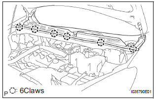
- Install the 6 claws and the cowl top ventilator louver sub-assembly.
4. INSTALL FR WIPER ARM LH
- Operate the wiper, and stop the windshield wiper motor assembly to the automatic stop position.

- Scrape off the serration part of the wiper arm with a round file or equivalent.
- Clean the wiper pivot serration with a wire brush.
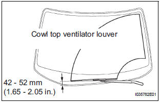
- Install the front wiper arm LH with the nut to the
position shown in the illustration.
Torque: 20 N*m (204 kgf*cm, 14.8 ft.*lbf)
HINT: Hold down the arm hinge by hand to fasten the nut.
5. INSTALL FR WIPER ARM RH
- Scrape off the serration part of the wiper arm with a round file or equivalent.
- Clean the wiper pivot serration with a wire brush.

- Install the front wiper arm RH with the nut to the
position shown in the illustration.
Torque: 20 N*m (205 kgf*cm, 15 ft.*lbf) HINT: Hold down the arm hinge by hand to fasten the nut.
- Operate the wiper while running the water or the washer fluid over the window, and check the wiping condition and that the front wiper does not hit against the vehicle body.
6. INSTALL FRONT WIPER ARM HEAD CAP
- Install the 2 caps.
 Inspection
1. INSPECT WINDSHIELD WIPER MOTOR ASSEMBLY
LO Operation Check
Connect the battery (+) to the terminal 1 (+1) of
the connector, the battery (-) to the terminal 5
(E) of th ...
 Front wiper rubber
COMPONENTS
REMOVAL
1. REMOVE FRONT WIPER BLADE
Remove the front wiper blade from the front wiper
arm LH.
NOTICE:
Do not fold down the front wiper arm with the
front wiper blade ...
Other materials:
Installation
1. INSTALL LOWER BALL JOINT ASSEMBLY FRONT LH
(a) Install the lower ball joint assembly front LH and
tighten the nut.
Torque: 123 N*m (1,250 kgf*cm, 91 ft.*lbf)
(b) Install a new cotter pin.
NOTICE:
If the holes for the cotter pin are not aligned,
tighten the nut further up to 60°.
2. INS ...
Terminals of ECU
1. CHECK DRIVER SIDE J/B ASSEMBLY (MULTIPLEX NETWORK BODY ECU)
Disconnect the 1C, 1J, 1L, 1K, 1P, B6, B7 and B9 J/
B connectors.
Measure the voltage and resistance according to
the value(s) in the table below.
Standard
HINT:
If the result is not as specified ...
Open in Side Squib RH Circuit
DTC B0111/44 Open in Side Squib RH Circuit
DESCRIPTION
The side squib RH circuit consists of the center airbag sensor assembly and
the front seat side airbag
assembly RH.
The circuit instructs the SRS to deploy when deployment conditions are met.
DTC B0111/44 is recorded when an open circ ...