Toyota Sienna Service Manual: Terminals of ECU
1. CHECK DRIVER SIDE J/B ASSEMBLY (MULTIPLEX NETWORK BODY ECU)
- Disconnect the 1C, 1J, 1L, 1K, 1P, B6, B7 and B9 J/ B connectors.

- Measure the voltage and resistance according to the value(s) in the table below.
Standard
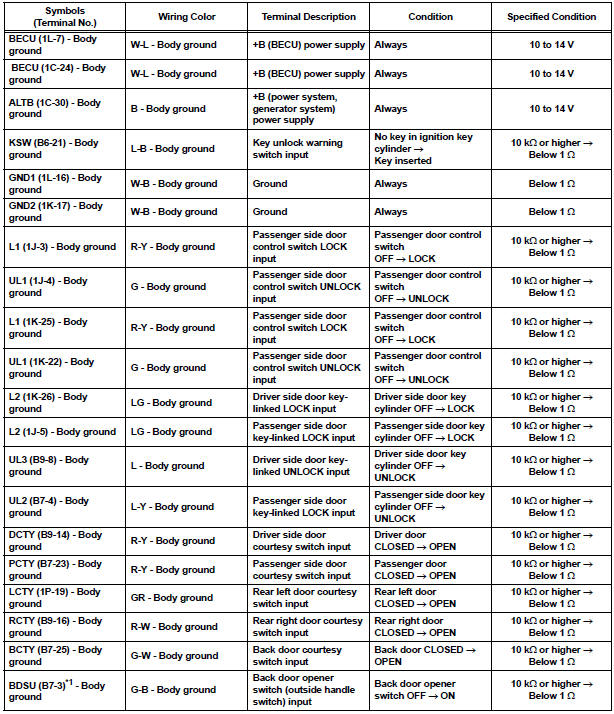
HINT:
- If the result is not as specified, there may be a malfunction on the wire harness side.
- *1: w/o Power back door
- Reconnect the J/B and ECU connectors and measure the voltage according to the value(s) in the table below.
Standard voltage


HINT:
- *1: w/o Power Back Door
- Use an oscilloscope to check the output voltages of terminals LSWD, LSWP, LSWL and LSWR.
- If the result is not as specified, the J/B (body ECU) may have a malfunction.
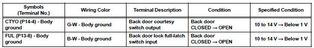
2. CHECK POWER BACK DOOR ECU (w/ Power back door system)
- Disconnect the P13 and P14 ECU connectors.

- Measure the voltage and resistance according to the value(s) in the table below.
Standard

HINT: If the result is not as specified, there may be a malfunction on the wire harness side.
- Reconnect the ECU connectors and measure the voltage according to the value(s) in the table below.
Standard voltage
HINT: If the result is not as specified, the ECU may have a malfunction.
 Problem symptoms table
HINT:
Inspect the fuse and relay before investigating the suspected
areas shown in the table below.
POWER DOOR LOCK CONTROL SYSTEM
...
 Diagnosis system
1. CHECK DLC3
The vehicle's ECU uses ISO 15765-4 for
communication protocol. The terminal arrangement
of the DLC3 complies with SAE J1962 and matches
the ISO 15765-4 format.
...
Other materials:
Transmitter battery
REPLACEMENT
1. REMOVE TRANSMITTER BATTERY
NOTICE:
Special caution should be taken for handling each
component as they are precision electronic
components.
Using a coin or the equivalent, pry out the
transmitter case.
NOTICE:
Do not forcibly pry out the case.
Re ...
A/F Sensor Circuit Slow Response
DTC P2A00 A/F Sensor Circuit Slow Response (Bank 1
Sensor 1)
DTC P2A03 A/F Sensor Circuit Slow Response (Bank 2
Sensor 1)
HINT:
DTC P2A00 indicates malfunctions related to the bank 1 A/F sensor.
DTC P2A03 indicates malfunctions related to the bank 2 A/F sensor.
Bank 1 r ...
Removal
1. DISCONNECT CABLE FROM NEGATIVE BATTERY
TERMINAL
CAUTION: Wait for 90 seconds after disconnecting the cable
to prevent the airbag working.
2. REMOVE INSTRUMENT CLUSTER FINISH PANEL SUB-ASSEMBLY
Disengage the 4 clips and remove the instrument
cluster finish panel sub-assembly.
...