Toyota Sienna Service Manual: Memory Switch Circuit
DESCRIPTION
When the seat memory switch M1 or M2 is pressed, the position control ECU & switch (Seat ECU) transmits a signal of the memorized mirror position to the outer mirror control ECU. Then, the outer mirror control ECU drives the mirror motor.
HINT: The power mirror control system is a part of the multiplex communication system. This system features shared communication wiring that reduces the wiring complexity of the communication lines. The first step in any repair is to confirm the proper operation of the communication system. Proceed with troubleshooting after the communication has been verified (See the Multiplex Communication System).
WIRING DIAGRAM

INSPECTION PROCEDURE
1 READ VALUE OF INTELLIGENT TESTER
- Connect the intelligent tester to the DLC3.
- Ignition switch on.
- Enter the following menus: DIAGNOSIS / ENHANCED OBD II / DATA LIST.
- Check the DATA LIST for proper function of the seat memory switch.
D-SEAT

OK: Tester displayed MEM.
2 INSPECT SEAT MEMORY SWITCH
- Remove the seat memory switch.
- Measure the resistance according to the value(s) in the table below when the switch is operated.
Standard resistance

3 CHECK HARNESS AND CONNECTOR (SEAT MEMORY SWITCH - OUTER MIRROR CONTROL ECU)
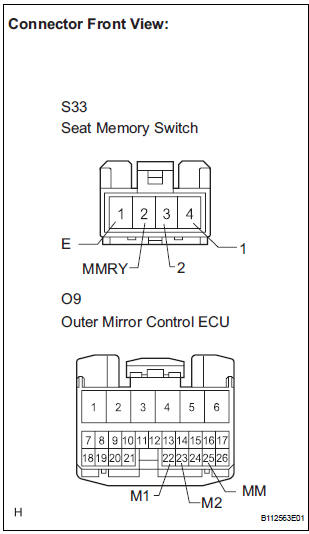
- Disconnect the S33 switch connector.
- Disconnect the O9 ECU connector.
- Measure the resistance according to the value(s) in the table below.
Resistance

REPLACE OUTER MIRROR CONTROL ECU
 Position Sensor Circuit
DESCRIPTION
When SET and 1 or 2 are pressed, the position sensor detects the mirror
position and sends the signal to
the outer mirror control ECU. Then when position 1 or 2 is pressed, the outer
...
 Power Source Circuit
DESCRIPTION
This is the power source circuit for the outer mirror control ECU.
WIRING DIAGRAM
INSPECTION PROCEDURE
1 INSPECT OUTER MIRROR CONTROL ECU (POWER SOURCE)
Disconnect the O9 o ...
Other materials:
Inspection
1. INSPECT REAR SPEED SENSOR
(a) Remove the seat cushion and seatback.
(b) Disconnect the speed sensor connector.
(c) Measure the resistance between terminals 1 and 2
of the speed sensor connector
OK:
Resistance:
1.1 +- 0.2 kΩ at 25 +- 5 °C
(d) Measure the resistance between ea ...
Operating the HomeLink
Press the appropriate HomeLink® button. The HomeLink® indicator
light on the HomeLink® transceiver should turn on.
The HomeLink® continues to send a signal for up to 20 seconds as long as
the button is pressed.
Reprogramming a HomeLink® button
Press and hold the desired HomeLink® button ...
Reassembly
1. INSTALL 2ND BRAKE PISTON O-RING
(a) Coat 2 new O-rings with ATF, and install them in the
2nd brake piston.
NOTICE:
Make sure that the O-ring is not twisted or
pinched.
2. INSTALL 2ND BRAKE PISTON
(a) Coat the 2nd brake piston with ATF, and install it to
the 2nd brake cylinder.
NO ...