Toyota Sienna Service Manual: Occupant Classification ECU Malfunction
DTC B1795 Occupant Classification ECU Malfunction
DESCRIPTION
DTC B1795 is recorded when a malfunction is detected in the occupant classification ECU.
Troubleshoot DTC B1771 first when the DTCs B1771 and B1795 are output simultaneously.
|
DTC No. |
DTC Detecting Condition |
Trouble Area |
|
B1795 |
|
|
INSPECTION PROCEDURE
1 CHECK DTC
- Turn the ignition switch to the ON position, and wait for at least 10 seconds.
- Check the DTCs (35).
Result:
A:
DTC B1795 is output.
B:
DTCs B1771 and B1795 are output.
HINT: Codes other than DTC B1771 and B1795 may be output at this time, but they are not related to this check.
2 CHECK FUSE
- Measure the resistance of the ECU-B fuse.
Resistance: Below 1 Ω
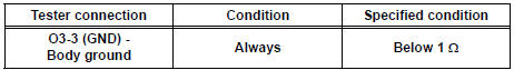
3 CHECK WIRE HARNESS (SOURCE VOLTAGE)

- Turn the ignition switch to the LOCK position.
- Disconnect the negative (-) terminal cable from the battery, and wait for at least 90 seconds.
- Disconnect the connector from the occupant classification ECU.
- Connect the negative (-) terminal cable to the battery.
- Turn the ignition switch to the ON position.
- Measure the voltage according to the value(s) in the table below.
Standard voltage

- Turn the ignition switch to the LOCK position.
- Measure the resistance according to the value(s) in the table below.
Standard resistance
4 REPLACE OCCUPANT CLASSIFICATION ECU
- Turn the ignition switch to the LOCK position.
- Disconnect the negative (-) terminal cable from the battery, and wait for at least 90 seconds.
- Replace the occupant classification ECU
5 PERFORM ZERO POINT CALIBRATION
- Connect the negative (-) terminal cable to the battery.
- Connect the intelligent tester to the DLC3.
- Turn the ignition switch to the ON position.
- Using the intelligent tester, perform "Zero point calibration" (28).
OK: "COMPLETED" is displayed.
6 PERFORM SENSITIVITY CHECK
- Using the intelligent tester, perform "Sensitivity check" (28).
Standard value: 27 to 33 kg (59.52 to 72.75 lb)
END
 Open in Occupant Classification ECU Battery
Positive Line
Open in Occupant Classification ECU Battery
Positive Line
DTC B1794 Open in Occupant Classification ECU Battery
Positive Line
DESCRIPTION
This circuit consists of the occupant classification ECU and the power source
circuit (battery, fuse, wire
harness ...
 Sleep Operation Failure of Occupant Classification
ECU
Sleep Operation Failure of Occupant Classification
ECU
DTC B1796 Sleep Operation Failure of Occupant Classification
ECU
DESCRIPTION
During sleep mode, the occupant classification ECU reads the condition of
each sensor while the ignition
switch is of ...
Other materials:
Precaution
1. INITIALIZATION
NOTICE:
Perform RESET MEMORY (AT initialization) when
replacing the automatic transaxle assembly, engine
assembly or ECM.
Perform REGISTRATION (VIN registration) when
replacing the ECM.
HINT:
Initialization cannot be completed by only removing the
batt ...
A/F sensor and ho2s monitors
(a) Preconditions
The monitor will not run unless:
2 minutes or more have elapsed since the engine
was started.
The Engine Coolant Temperature (ECT) is 75°C
(167°F) or more.
Cumulative driving time at a vehicle speed of 30
mph (48 km/h) or more exceeds 6 minutes.
Air-fuel ratio fe ...
Rear view monitor
system
The rear view monitor system assists the driver by displaying an
image of the view behind the vehicle and guide lines while backing
up, for example while parking.
The screen illustrations used in this text are intended as examples,
and may differ from the image that is actually displayed on the
...