Toyota Sienna Service Manual: Occupant Classification System Malfunction
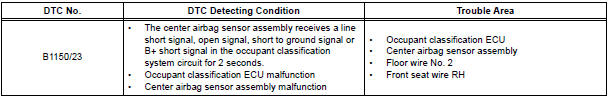
DTC B1150/23 Occupant Classification System Malfunction
DESCRIPTION
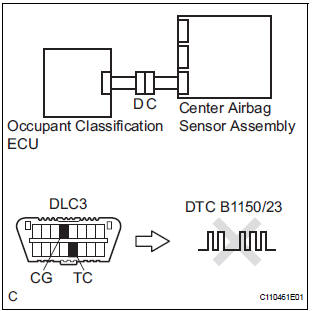
The occupant classification system circuit consists of the center airbag sensor assembly and the occupant classification ECU.
If the center airbag sensor assembly receives signals from the occupant classification ECU, it determines whether or not the front passenger airbag, the front seat side airbag RH, and front seat belt pretensioner RH should be operated.
DTC B1150/23 is recorded when a malfunction is detected in the occupant classification system circuit.
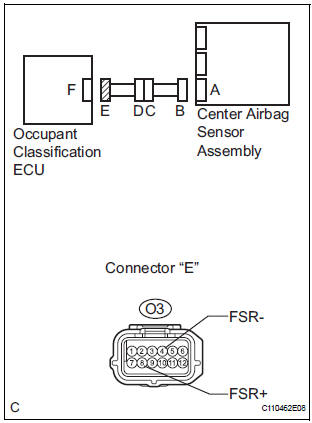
WIRING DIAGRAM

INSPECTION PROCEDURE
1 CHECK DTC (OCCUPANT CLASSIFICATION ECU)
- Turn the ignition switch to the ON position, and wait for at least 10 seconds.
- Using the intelligent tester, check the DTCs of the occupant classification ECU.
OK: DTC is not output
2 CHECK DTC (CENTER AIRBAG SENSOR ASSEMBLY)
- Turn the ignition switch to the ON position, and wait for at least 60 seconds.
- Clear the DTCs stored in memory.
- Turn the ignition switch to the LOCK position.
- Turn the ignition switch to the ON position, and wait for at least 60 seconds.
- Check the DTCs.
OK: DTC B1150/23 is not output.
HINT: Codes other than code B1150/23 may be output at this time, but they are not related to this check.
USE SIMULATION METHOD TO CHECK
3 CHECK CONNECTION OF CONNECTORS
- Turn the ignition switch to the LOCK position.
- Disconnect the negative (-) terminal cable from the battery, and wait for at least 90 seconds.
- Check that the connectors are properly connected to the center airbag sensor assembly and the occupant classification ECU.
OK: The connectors are connected.
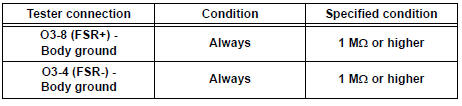
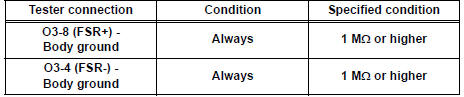
4 CHECK OCCUPANT CLASSIFICATION ECU CIRCUIT (SHORT TO GROUND)

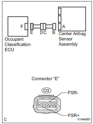
- Disconnect the connectors from the center airbag sensor assembly and the occupant classification ECU.
- Measure the resistance according to the value(s) in the table below.
Standard resistance
5 CHECK OCCUPANT CLASSIFICATION ECU CIRCUIT (SHORT TO B+)
- Connect the negative (-) terminal cable to the battery, and wait for at least 2 seconds.
- Turn the ignition switch to the ON position.
- Measure the voltage according to the value(s) in the table below.
Standard voltage

6 CHECK OCCUPANT CLASSIFICATION ECU CIRCUIT (SHORT)
- Turn the ignition switch to the LOCK position.
- Disconnect the negative (-) terminal cable from the battery, and wait for at least 90 seconds.
- Measure the resistance according to the value(s) in the table below.
Standard resistance

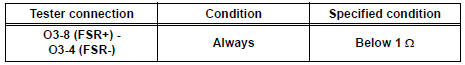
7 CHECK OCCUPANT CLASSIFICATION ECU CIRCUIT (OPEN)

- w/ Side airbag:
Using a service wire, connect A22-1 (FSR+) and A22-2
(FSR-) of connector "B".
NOTICE: Do not forcibly insert a service wire into the terminals of the connector when connecting.
- w/o Side airbag:
Using a service wire, connect A22-3 (FSR+) and A22-10
(FSR-) of connector "B".
NOTICE: Do not forcibly insert a service wire into the terminals of the connector when connecting.
- Measure the resistance according to the value(s) in the table below.
Standard resistance

8 CHECK FRONT SEAT WIRE RH (SHORT TO GROUND)
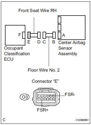
- Disconnect the front seat wire RH connector from the floor wire No. 2.
- Measure the resistance according to the value(s) in the table below.
Standard resistance
REPAIR OR REPLACE FLOOR WIRE NO.2
9 CHECK FRONT SEAT WIRE RH (SHORT TO B+)
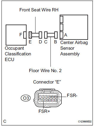
- Turn the ignition switch to the LOCK position.
- Disconnect the negative (-) terminal cable from the battery, and wait for at least 90 seconds.
- Disconnect the front seat wire RH connector from the floor wire No. 2.
- Connect the negative (-) terminal cable to the battery, and wait for at least 2 seconds.
- Turn the ignition switch to the ON position.
- Measure the voltage according to the value(s) in the table below.
Standard voltage

REPAIR OR REPLACE FLOOR WIRE NO.2
10 CHECK FRONT SEAT WIRE RH (SHORT)

- Disconnect the front seat wire RH connector from the floor wire No. 2.
- Measure the resistance according to the value(s) in the table below.
Standard resistance

REPAIR OR REPLACE FLOOR WIRE NO.2
11 CHECK FRONT SEAT WIRE RH (OPEN)

- Disconnect the service wire from connector "B".
- Disconnect the front seat wire RH connector from the floor wire No. 2.
- w/ Power seat:
Using a service wire, connect BO1-3 (FSR+) and BO1-5
(FSR-) of connector "D".
NOTICE: Do not forcibly insert a service wire into the terminals of the connector when connecting.
- w/o Power seat:
Using a service wire, connect BM1-3 (FSR+) and BM1-2
(FSR-) of connector "D".
NOTICE: Do not forcibly insert a service wire into the terminals of the connector when connecting.
- Measure the resistance according to the value(s) in the table below.
Standard resistance
REPAIR OR REPLACE FLOOR WIRE NO.2
 Front Airbag Sensor LH Circuit Malfunction
DTC B1149/37 Front Airbag Sensor LH Circuit Malfunction
DESCRIPTION
The front airbag sensor LH circuit consists of the center airbag sensor
assembly and front airbag sensor
LH.
If the center a ...
 Passenger Airbag ON/OFF Indicator Circuit
Malfunction
Passenger Airbag ON/OFF Indicator Circuit
Malfunction
DTC B1152/28 Passenger Airbag ON/OFF Indicator Circuit
Malfunction
DESCRIPTION
The passenger airbag ON/OFF indicator circuit consists of the center airbag
sensor assembly and
passenger airba ...
Other materials:
GPS Antenna Error/ GPS Antenna Power Source Error
DTC 58-40 GPS Antenna Error
DTC 58-41 GPS Antenna Power Source Error
DTC 80-40 GPS Antenna Error
DTC 80-41 GPS Antenna Power Source Error
DESCRIPTION
DTC No.
DTC Detection Condition
Trouble Area
58-40
GPS antenna error
Wire harness
GPS ...
Weight limits
The gross trailer weight must never exceed 3500 lb. (1588 kg).*
The gross combination weight must never exceed the GCWR
described below.
2WD models: 8900 lb. (4037 kg)*
AWD models: 8990 lb. (4078 kg)*
The gross vehicle weight must
never exceed the GVWR indicated
on the Certifi ...
Power Back Door does not Operate
DESCRIPTION
The power back door operates only when the power back door main
switch is ON. The power back
door ECU controls the power back door by activating the back door motor
(built into the power back
door drive unit) to open / close the back door.
A request signal from the satell ...