Toyota Sienna Service Manual: Operation check
1. CHECK WINDOW LOCK SWITCH
- Check that the passenger side power window and slide door power window operation is disabled when the window lock switch of the power window master switch is pressed.
- Check that the passenger side power window and slide door power windows can be operated when the window lock switch is pressed again.
2. CHECK MANUAL UP/DOWN FUNCTION
- Check that the driver side power window can be operated using the AUTO (driver side) switch of the power window master switch as follows:
Standard

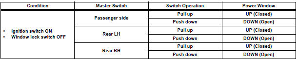
- Check that the passenger power window and slide door power windows can be operated using each power window regulator switch as follows:
Standard
3. CHECK AUTO UP/DOWN FUNCTION
- Check that the driver side power window can be operated using the AUTO (driver side) switch of the power window master switch as follows:
Standard

4. CHECK REMOTE MANUAL UP/DOWN FUNCTION
- Check that the passenger side power window and slide door power window can be operated using each switch of the power window master switch as follows:
Standard

5. CHECK MANUAL DOWN FUNCTION VIA TRANSMITTER
- Check that all power windows and sliding roof (standard type only) operate as follows when operating the transmitter:
Standard

HINT: For a sign for starting operation, the wireless door lock buzzer sounds once (answer-back).
6. CHECK POWER WINDOW OPERATION FUNCTION AFTER IGNITION SWITCH IS TURNED OFF
- When both of the following conditions are fulfilled, check that the power windows can be operated even after the ignition switch is turned off.
- Within 45 seconds after the ignition switch is turned off.
- The front doors are closed.
7. CHECK JAM PROTECTION FUNCTION

HINT: The jam protection function prevents any part of your body from getting caught by accident between the door frame and the door glass during power window operation.
NOTICE: If the power window motor has been reset, raise and lower the door glass several times using MANUAL function before performing the check.
- Check that the door glass goes down by approx. 50 mm (1.97 in.) right when something gets caught between the door frame and door glass during power window operation. However, when the opening between the door frame and the door glass is less than 200 mm (7.87 in.), the door glass keeps going down until the operation reaches 200 mm (7.87 in.) and stops there.
- AUTO UP
- AUTO UP operation after the ignition switch OFF
- MANUAL UP operation after the ignition switch OFF
8. CHECK POWER WINDOW FAIL-SAFE FUNCTION
- If there is a malfunction in the pulse sensor of the power window motor, the power window function will be restricted to partial operation.


*: However, manual UP function of the power window is operative when fully pulling up the power window switch.
 How to proceed with
troubleshooting
How to proceed with
troubleshooting
HINT:
Troubleshoot in accordance with the procedures on the
following pages.
1 VEHICLE BROUGHT TO WORKSHOP
2 CUSTOMER PROBLEM ANALYSIS CHECK AND SYMPTOM CHECK
3 PROBLEM SYMPTOMS TABLE
When pr ...
 Customize parameters
HINT:
The following item can be customized.
NOTICE:
After confirming whether the items requested by the
customer are applicable or not for customization,
perform the customize operatio ...
Other materials:
Reassembly
1. INSTALL REAR DOOR WIRE SUB-ASSEMBLY LH
Install the wire.
NOTICE:
When installing the wire, push the areas where
the clips are installed in order to prevent
damage and deformation.
Install the 2 screws
2. INSTALL REAR DOOR LOCK ASSEMBLY LH
Apply MP grease to the slidin ...
Fuel Pump Control Circuit
DESCRIPTION
The FUEL PUMP relay switches the fuel pump speed according to the engine
conditions. The fuel pump
operates when the ECM receives the starter-operating signal (STA) and
crankshaft-rotating signal (NE).
The FUEL PUMP relay is turned ON while the engine is idling or operating at l ...
Installation with LATCH system (second seat)
Fold the seatback while pulling
the lever and move to the rearmost
recline position.
Widen the gap between the seat cushion and seatback slightly.
Type A
Latch the hooks of the lower
straps onto the LATCH
anchors. If the child restraint
has a top tether strap, the ...