Toyota Sienna Service Manual: Precaution
1. PRECAUTION
(a) Before inspecting and repairing the fuel system, disconnect the cable from the negative (-) battery terminal.
(b) Do not smoke or work near fire when handling the fuel system.
(c) Keep gasoline away from rubber or leather parts.
2. DISCHARGE FUEL SYSTEM PRESSURE (*1)
CAUTION:
|

a) Remove the circuit opening relay from the engine room relay block.
(b) Start the engine.
(c) After the engine stops, turn the engine switch off.
HINT: DTC P0171/25 (fuel problem) may be detected.
(d) Crank the engine again. Check that the engine does not start.
(e) Remove the fuel tank cap to discharge pressure from the fuel tank.
(f) Disconnect the cable from the negative (-) battery terminal.
(g) Reinstall the circuit opening relay.
3. FUEL SYSTEM
(a) When disconnecting the high pressure fuel line, a large amount of gasoline will spill out, so observe the following procedures:
(1) Discharge the fuel system pressure(*1).
(2) Disconnect the fuel pump tube (See page FU- 30).
(3) Drain the fuel that remains in the fuel pump tube.
(4) To protect the disconnected fuel pump tube from damage and contamination, cover it with a plastic bag.
(5) Put a container under the connectors.

(b) Observe the following precautions when removing and installing the fuel injectors:
(1) Never reuse an O-ring.
(2) When placing a new O-ring on the injector, do not damage the O-ring.
(3) Coat a new O-ring with spindle oil or gasoline before installing it.

| NOTICE: Do not use engine oil, gear oil or brake fluid. |
(c) Install the injector to the delivery pipe and the lower intake manifold as shown in the illustration.

| NOTICE: Before installing the injector, be sure to apply appropriate lubricant or gasoline to the place where the delivery pipe or cylinder head contacts the injector O-rings. |
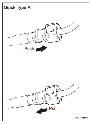
(d) Observe the following precautions when disconnecting the fuel tube connectors (Quick type A):

(1) Remove the No. 1 fuel pipe clamp.
(2) Check that there is no dirt or other foreign objects on the pipe and around the connector before disconnecting them. Clean them if necessary.

(3) Disconnect the connector from the pipe by hand.
(4) If the connector and the pipe are stuck, push in and pull on the connector to release it. Pull the connector out of the pipe carefully.
(5) Check that there is no dirt or other foreign objects on the sealing surface of the disconnected pipe. Clean the surfaces if necessary.

(6) Do not damage the disconnected pipe or connector. Prevent entry of foreign objects by covering the connectors with plastic bags.
(e) Observe the following precautions when connecting the fuel tube connectors (Quick Type A):
(1) Check if there is any damage or foreign objects on the connecting parts of the pipes.
(2) Line up the 2 parts of the pipes to be connected, and push them together until the connector makes a "click" sound. If the pipe is difficult to push into the connector, apply a small amount of clean engine oil to the tip of the pipe and reinsert it.
(3) After connecting the pipes, check that the pipe and connector are securely connected by pulling on them.
(4) Check for fuel leaks.
(f) Observe the following precautions when disconnecting the fuel tube connector (Quick type B): (1) Before disconnecting the connector, clean off any dirt that may be present.
(2) Pinch the tabs of the fuel tube retainer to disengage the 2 claws. Push the retainer down as shown in the illustration.
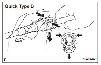
HINT: Be sure to disconnect the connector by hand.
(3) If the connector and pipe are stuck, hold the fuel pipe by hand, push, and pull on the connector.
Pull the 2 pipes apart to separate the connector.
(4) Check if there is any dirt or any other foreign objects on the sealing surfaces of the disconnected pipes. Clean the sealing surfaces if necessary.

(5) Do not damage the disconnected pipe or connector. Prevent entry of foreign objects by covering the connectors with plastic bags.

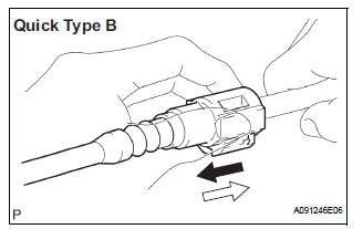
(g) Observe the following precautions when connecting the fuel tube connector (Quick Type B):
(1) Line up the 2 parts of the pipes to be connected, and fully push the fuel tube connector and pipe together until they are fully seated. Next, push the retainer into the connector until its claws lock. If the pipe is difficult to push in to the connector, apply a small amount of clean engine oil to the tip of the pipe and reinsert it.
(2) After connecting the pipes, check that the pipe and connector are securely connected by pulling on them.
(3) Check for fuel leaks.
(h) Observe the following precautions when handling a nylon tube:
CAUTION:
|
4. INSPECT FOR FUEL LEAK
(a) Check that there are no fuel leaks from the fuel system after doing any maintenance or repairs (See page FU-7).
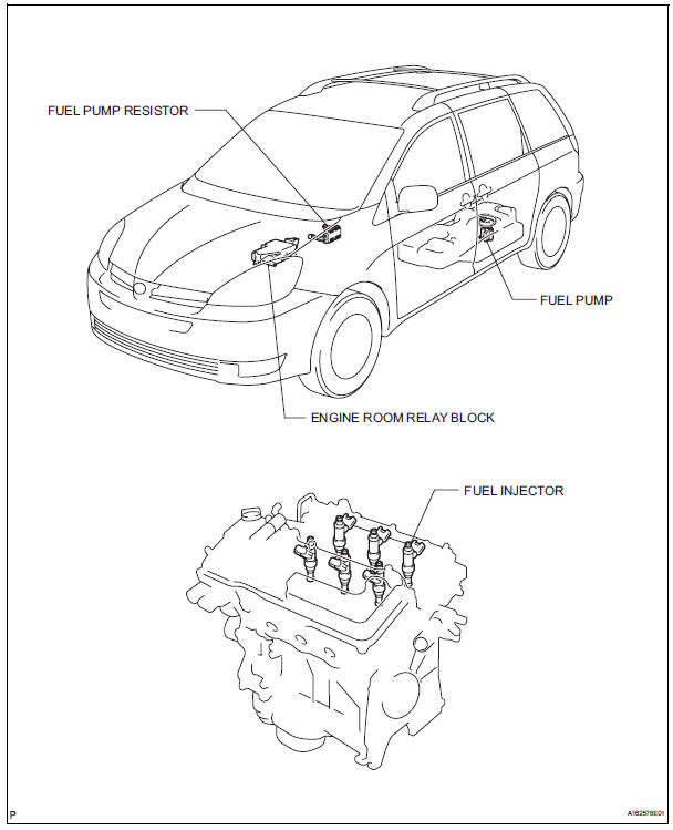
PARTS LOCATION
SYSTEM DIAGRAM

 Fuel system
...
 On-vehicle inspection
1. INSPECT FOR FUEL PUMP OPERATION AND FUEL
LEAK
(a) Check fuel pump operation.
(1) Connect the intelligent tester to the DLC3.
(2) Turn the engine switch on (IG) and push the
intelligent teste ...
Other materials:
Reassembly
1. INSTALL GENERATOR ROTOR ASSEMBLY
(a) Place the drive end frame on the clutch pulley.
(b) Install the generator rotor assembly to the drive end
frame.
(c) Place a new generator washer on the generator
rotor.
2. INSTALL GENERATOR COIL ASSEMBLY
(a) Using a deep socket wrench (21 ...
No. 1 Ultrasonic sensor
COMPONENTS
REMOVAL
1. REMOVE FRONT FENDER LINER LH
2. REMOVE FRONT FENDER LINER RH
3. REMOVE FRONT BUMPER COVER
4. REMOVE REAR BUMPER COVER (2)
5. REMOVE NO. 1 ULTRASONIC SENSOR RETAINER
Remove the No. 1 ultrasonic sensor retainer as
shown in the illustration
6. REMOVE ...
Mute Signal Circuit between Radio Receiver and Stereo Component
Amplifier
DESCRIPTION
This circuit sends a signal to the stereo component amplifier to mute noise.
Because of that, the noise
produced by changing the sound source ceases.
If there is an open in the circuit, noise can be heard from the speakers when
changing the sound source.
If there is a short i ...