Toyota Sienna Service Manual: Reassembly
1. INSTALL GENERATOR ROTOR ASSEMBLY

(a) Place the drive end frame on the clutch pulley.
(b) Install the generator rotor assembly to the drive end frame.

(c) Place a new generator washer on the generator rotor.
2. INSTALL GENERATOR COIL ASSEMBLY

(a) Using a deep socket wrench (21 mm) and a press, slowly press in the generator coil assembly.

(b) Install the 4 bolts.
Torque: 5.8 N*m (59 kgf*cm, 51 in.*lbf)
3. INSTALL GENERATOR BRUSH HOLDER ASSEMBLY

(a) While pushing the 2 brushes into the generator brush holder assembly, insert a φ1.0 mm (0.039 in.) pin into the brush holder hole.

(b) Install the brush holder assembly to the generator coil with the 2 screws.
Torque: 1.8 N*m (18 kgf*cm, 16 in.*lbf) (c) Pull out the pin from the generator brush holder.
4. INSTALL GENERATOR TERMINAL INSULATOR
(a) Install the terminal insulator to the generator coil.
| NOTICE: Pay attention to installation direction of the terminal insulator. |
5. INSTALL GENERATOR REAR END COVER

(a) Install the generator rear end cover to the generator coil with the 3 nuts.
Torque: 4.6 N*m (47 kgf*cm, 41 in.*lbf)
6. INSTALL GENERATOR CLUTCH PULLEY
(a) Temporarily install the clutch pulley onto the rotor shaft.

(b) Set SST (A) and (B).
SST 09820-63020

(c) Clamp SST (A) in a vise.
| NOTICE: Be sure to fix the flat surface of SST (A) in a vise. |

(d) Place the rotor shaft end into SST (A).

(e) Fit SST (B) to the clutch pulley.
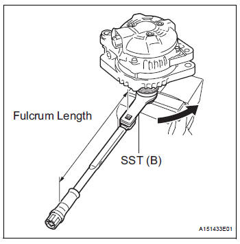
(f) Tighten the pulley by turning SST (B) in the direction shown in the illustration.
Torque: without SST 110 N*m (1125 kgf*cm, 81 ft.*lbf)
with SST 84 N*m (857 kgf*cm, 62 ft.*lbf)
NOTICE:
|
(g) Remove the generator assembly from SST.
(h) Check that the clutch pulley rotates smoothly.
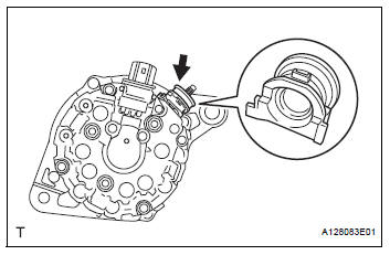
(i) Install a new clutch pulley cap to the clutch pulley.
 Replacement
1. REPLACE GENERATOR DRIVE END FRAME BEARING
(a) Remove the 4 screws and retainer plate from the
drive end frame.
(b) Using SST and a hammer, tap out the drive end
frame bearing from the d ...
 Installation
1. Install generator assembly
(a) Install the bracket with the bolt.
Torque: 20 N*m (204 kgf*cm, 15 ft.*lbf)
(b) Install the wire harness clamp stay.
Torque: 8.4 N*m (86 kgf*cm, 74 in. ...
Other materials:
Reassembly
1. INSTALL SEAT POSITION AIRBAG SENSOR (for Driver Seat)
2. INSTALL LUMBAR SUPPORT ADJUSTER
ASSEMBLY LH
Install the seat side table leg cover.
3. INSTALL FRONT SEAT CUSHION SHIELD LOWER LH
Install the front seat cushion shield lower LH with
the screw.
4. INSTALL FRONT SEAT CU ...
Removal
1. REMOVE ENGINE ASSEMBLY WITH TRANSAXLE
HINT:
See page EM-26
2. SECURE ENGINE (See page EM-37)
3. REMOVE GENERATOR ASSEMBLY (See page CH-17)
4. REMOVE COMPRESSOR AND MAGNETIC CLUTCH
(See page AC-227)
5. REMOVE NO. 1 ENGINE FRONT MOUNTING
BRACKET LH (See page EM-42)
6. REMOVE NO. 2 IDLER PU ...
Short to GND in Rear Curtain Shield Squib RH
Circuit
DTC B1632/81 Short to GND in Rear Curtain Shield Squib RH
Circuit
DESCRIPTION
The rear curtain shield squib RH circuit consists of the center airbag sensor
assembly and the curtain
shield airbag assembly RH.
The circuit instructs the SRS to deploy when deployment conditions are met.
DTC ...