Toyota Sienna Service Manual: Pressure Control Solenoid "D" Electrical (Shift Solenoid Valve SLT)
DESCRIPTION
The linear solenoid valve (SLT) controls the transmission line pressure for smooth transmission operation based on signals from the throttle position sensor and the vehicle speed sensor. The ECM adjusts the duty cycle of the SLT solenoid valve to control hydraulic line pressure coming from the primary regulator valve. Appropriate line pressure assures smooth shifting with varying engine outputs.
(*): Duty Ratio The duty ratio is the ratio of the period of continuity in one cycle.
For example, if A is the period of continuity in one cycle, and B is the period
of non-continuity, then
Duty Ratio = A/(A + B) x 100(%)

MONITOR DESCRIPTION
When an open or short in the linear solenoid valve (SLT) circuit is detected, the ECM interprets this as a fault. The ECM will turn on the MIL and store the DTC.
MONITOR STRATEGY
TYPICAL ENABLING CONDITIONS

TYPICAL MALFUNCTION THRESHOLDS

COMPONENT OPERATING RANGE

WIRING DIAGRAM

INSPECTION PROCEDURE
1 INSPECT TRANSMISSION WIRE (SLT)

(a) Disconnect the transmission wire connector from the transaxle.
(b) Measure the resistance according to the value(s) in the table below.
Standard resistance
(c) Measure the resistance according to the value(s) in the table below.
Standard resistance (Check for short)


2 CHECK HARNESS AND CONNECTOR (TRANSMISSION WIRE - ECM)

(a) Connect the transmission wire connector to the transaxle.
(b) Disconnect the ECM connector.
(c) Measure the resistance according to the value(s) in the table below.
Standard resistance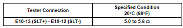
(d) Measure the resistance according to the value(s) in the table below.
Standard resistance (Check for short)


REPLACE ECM
3 INSPECT SHIFT SOLENOID VALVE SLT

(a) Remove the shift solenoid valve (SLT).
(b) Measure the resistance according to the value(s) in the table below.
Standard resistance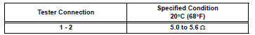
(c) Connect the positive (+) lead with a 21 W bulb to terminal 2 and the negative (-) lead to terminal 1 of the solenoid valve connector, then check the movement of the valve.
OK: The solenoid makes an operating sound.


REPAIR OR REPLACE TRANSMISSION WIRE
 Pressure Control Solenoid "D" Performance (Shift
Solenoid Valve SLT)
Pressure Control Solenoid "D" Performance (Shift
Solenoid Valve SLT)
SYSTEM DESCRIPTION
The linear solenoid valve (SLT) controls the transmission line pressure for
smooth transmission operation
based on signals from the throttle position sensor and the vehicle spee ...
 Torque Converter Clutch Solenoid Circuit
DESCRIPTION
The shift solenoid valve DSL is turned "ON" and "OFF" by signals from the ECM
in order to control the
hydraulic pressure operation, the lock-up relay valve, whi ...
Other materials:
Cargo net hooks
Raise the hook to use.
Pattern 1
Pattern 2
NOTICE
To prevent damage to the cargo net hooks, avoid hanging things other
than
a cargo net on them.
Storage box (if equipped)
Engage the latch buckle. ...
Starter Relay Circuit High
DTC P0617 Starter Relay Circuit High
MONITOR DESCRIPTION
While the engine is being cranked, the positive battery voltage is applied to
terminal STA of the ECM.
If the ECM detects the Starter Control (STA) signal while the vehicle is being
driven, it determines that
there is a malfunction i ...
Installation
1. INSTALL NO. 2 REAR SEAT OUTER BELT ASSEMBLY
NOTICE:
Do not disassemble the retractor.
Check the degree of tilt when the No. 2 rear seat
outer belt assembly begins to lock the ELR.
Check that the belt does not lock within 15 of
tilt in all directions but that the be ...