Toyota Sienna Service Manual: Starter Relay Circuit High
DTC P0617 Starter Relay Circuit High
MONITOR DESCRIPTION
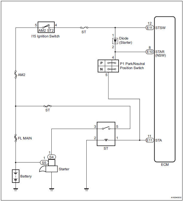
While the engine is being cranked, the positive battery voltage is applied to terminal STA of the ECM.
If the ECM detects the Starter Control (STA) signal while the vehicle is being driven, it determines that there is a malfunction in the STA circuit. The ECM then illuminates the MIL and sets the DTC.
This monitor runs when the vehicle is driven at 12.4 mph (20 km/h) for over 20 seconds.

MONITOR STRATEGY

TYPICAL ENABLING CONDITIONS

TYPICAL MALFUNCTION THRESHOLDS

WIRING DIAGRAM
INSPECTION PROCEDURE
HINT:
- The following troubleshooting flowchart is based on the premise that the engine is cranked normally. If the engine will not crank, proceed to the problem symptoms table
- Read freeze frame data using the intelligent tester. The ECM records vehicle and driving condition information as freeze frame data the moment a DTC is stored. When troubleshooting, freeze frame data can be helpful in determining whether the vehicle was running or stopped, whether the engine was warmed up or not, whether the air-fuel ratio was lean or rich, as well as other data recorded at the time of a malfunction
1 READ VALUE OF INTELLIGENT TESTER (STARTER SIGNAL)
- Connect the intelligent tester to the DLC3.
- Turn the ignition switch to the ON position and turn the tester on.
- Select the following menu items: DIAGNOSIS / ENHANCED OBD II / DATA LIST / ALL / STARTER SIG.
- Check the value displayed on the tester when the ignition switch is turned to the ON position and START position.
OK
2 INSPECT PARK/NEUTRAL POSITION SWITCH

- Inspect the Park/Neutral Position (PNP) switch.
- Disconnect the P1 PNP switch connector.
- Measure the resistance according to the value(s) in the table below.
Standard resistance

- Reconnect the PNP switch connector.
3 READ VALUE OF INTELLIGENT TESTER (STARTER SIGNAL)
- Connect the intelligent tester to the DLC3.
- Turn the ignition switch to the ON position and turn the tester on.
- Select the following menu items: DIAGNOSIS / ENHANCED OBD II / DATA LIST / ALL / STARTER SIG.
- Check the value displayed on the tester when the ignition switch is turned to the ON position and the START position.
OK
4 INSPECT IGNITION SWITCH ASSEMBLY
- Disconnect the I15 ignition switch connector.
- Measure the resistance according to the value(s) in the table below.
Standard resistance
- Reconnect the ignition switch connector.
5 READ VALUE OF INTELLIGENT TESTER (STARTER SIGNAL)
- Connect the intelligent tester to the DLC3.
- Turn the ignition switch to the ON position and turn the tester on.
- Select the following menu items: DIAGNOSIS / ENHANCED OBD II / DATA LIST / PRIMARY / STARTER SIG.
- Check the value displayed on the tester when the ignition switch is turned to the ON position and the START position
OK

REPAIR OR REPLACE HARNESS OR CONNECTOR (PNP SWITCH - STA TERMINAL OF ECM)
 Control Module Performance
DTC P0607 Control Module Performance
DESCRIPTION
The ECM continuously monitors its main and sub CPUs. This self-check ensures
that the ECM is
functioning properly. If outputs from the CPUs are di ...
 VIN not Programmed or Mismatch - ECM / PCM
DTC P0630 VIN not Programmed or Mismatch - ECM / PCM
DESCRIPTION
DTC P0630 is set when the Vehicle Identification Number (VIN) is not stored
in the Engine Control Module
(ECM) or the input VIN is ...
Other materials:
Installation
1. Install heated oxygen sensor (for bank 2
sensor 2) (see page ec-34)
2. Install front exhaust pipe assembly
(a) Install 2 new gaskets to the front exhaust pipe
assembly.
(b) Install the front exhaust pipe assembly with the 4
nuts.
Torque: 62 n*m (632 kgf*cm, 46 ft.*Lbf)
3. INSTALL CE ...
Brake Switch "A" Circuit
DTC P0571 Brake Switch "A" Circuit
DESCRIPTION
When the brake pedal is depressed, the stop light switch sends a signal to
the ECM. When the ECM
receives this signal, it cancels the cruise control. The fail-safe function
operates to enable normal driving
even if there is a malfuncti ...
Preparation 2gr-fe cooling
SST
RECOMMENDED TOOLS
EQUIPMENT
COOLANT
Capacity
Classification
11.3 liters (12.0 US qts, 10.0 Imp. qts)
Use only "TOYOTA Super Long Life Coolant" or similar high quality
ethylene glycol based non-silicate, non-amine, non-nitrite, non-borate
coolant ...