Toyota Sienna Service Manual: Radio and Navigation Assembly Communication Error
INSPECTION PROCEDURE
1 IDENTIFY THE COMPONENT SHOWN BY THE SUB-CODE
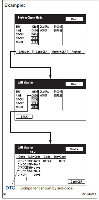
- Enter the diagnostic mode.
- Press the "LAN Mon" switch to change to "LAN Monitor" mode.
- Identify the component shown by the sub-code.
HINT:
- "110 (multi-display)" is the component shown by the sub-code in the example shown in the illustration.
- The sub-code will be indicated by its physical address.
- For the component list, refer to "DIAGNOSIS DISPLAY DETAILED DESCRIPTION"
2 CHECK POWER SOURCE CIRCUIT OF COMPONENT SHOWN BY SUB-CODE
- Inspect the power source circuit of the component shown
by the sub-code.
If the power source circuit is operating normally, proceed to the next step
Component Table:

3 CHECK RADIO AND NAVIGATION ASSEMBLY
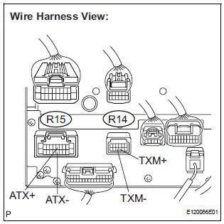
- Disconnect the radio and navigation assembly.
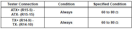
- Measure the resistance according to the value(s) in the table below.
Standard resistance
4 CHECK HARNESS AND CONNECTOR
HINT:
- Start the check from the circuit that is near the component shown by the sub-code first.
- For details of the connectors, refer to "TERMINALS OF ECU".
- Referring to the AVC-LAN wiring diagram below, check the AVC-LAN circuit between the radio and navigation assembly and the component shown by the sub-code.
- Disconnect all connectors between the radio and navigation assembly and the component shown by sub-code.
- Check for an open or short in the AVC-LAN circuit between the radio and navigation assembly and the component shown by the sub-code
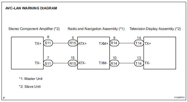
OK: There is no open or short circuit.
5 REPLACE COMPONENT SHOWN BY SUB-CODE
- Replace the component shown by the sub-code with a normal one and check if the same problem occurs again.
OK: Same problem does not occur.
END
 Stereo Component Amplifier Communication Error
INSPECTION PROCEDURE
1 IDENTIFY THE COMPONENT SHOWN BY THE SUB-CODE
Enter the diagnostic mode.
Press the "LAN Mon" switch to change to "LAN Monitor"
mode.
&nbs ...
 Television Display Assembly Communication Error
INSPECTION PROCEDURE
1 IDENTIFY THE COMPONENT SHOWN BY THE SUB-CODE
Enter the diagnostic mode.
Press the "LAN Mon" switch to change to "LAN Monitor"
mode.
&nbs ...
Other materials:
Front No. 2 speaker
COMPONENTS
ON-VEHICLE INSPECTION
1. INSPECT FRONT NO.2 SPEAKER
HINT:
Remove interior parts so that the front No.2 speaker can
be seen.
Check the speaker installation.
OK:
The speaker is securely installed.
If the result is not as specified, reinstall the front
No.2 speak ...
Precaution
1. REMOVAL AND INSTALLATION TIRE PRESSURE
WARNING VALVE AND TRANSMITTER
(a) When installing a tire, make sure that the tire
pressure warning valve and transmitter does not
interfere with the tire bead in order to prevent
damage to the tire pressure warning valve and
transmitter.
(b) After c ...
Adjustment
CAUTION:
Do not stare at the luminous portion of the laser
during adjustment. The intensity of the laser light is
low, but it may result in loss of sight.
If operation is not carried out as specified, there may
be a risk that you are exposed to hazardous radiation.
HINT:
...