Toyota Sienna Service Manual: Rear Air Conditioning Control Panel Circuit
DESCRIPTION
This is the rear A/C system control signal circuit as well as the power supply circuit of the rear A/C control assembly.
Pulse signals regarding rear A/C control panel switch operation are transmitted between the A/C amplifier and rear A/C control assembly.
WIRING DIAGRAM

INSPECTION PROCEDURE
1 CHECK HARNESS AND CONNECTOR (REAR A/C CONTROL ASSEMBLY - BATTERY)
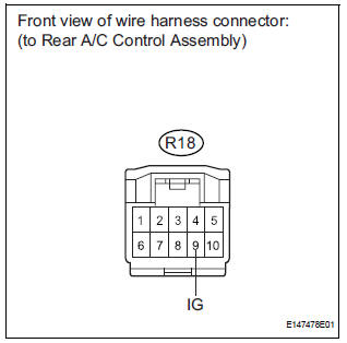
(a) Disconnect the connector from the rear A/C control assembly.
(b) Measure the voltage according to the value(s) in the table below.
Standard voltage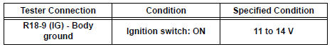

2 CHECK HARNESS AND CONNECTOR (REAR A/C CONTROL ASSEMBLY - BODY GROUND)
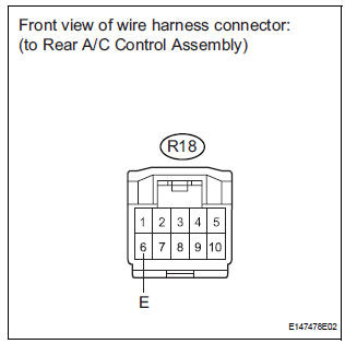
(a) Measure the resistance according to the value(s) in the table below.
Standard resistance 


3 CHECK HARNESS AND CONNECTOR (REAR A/C CONTROL ASSEMBLY - A/C AMPLIFIER)

(a) Disconnect the connector from the A/C amplifier.
(b) Measure the resistance according to the value(s) in the table below.
Standard resistance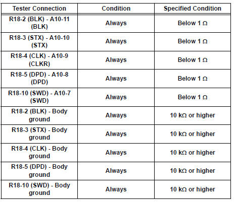


PROCEED TO NEXT CIRCUIT INSPECTION SHOWN IN PROBLEM SYMPTOMS TABLE
 Air Conditioning Compressor Magnetic Clutch Circuit
DESCRIPTION
When the A/C amplifier is turned on, a magnetic clutch ON signal is sent from
the MGC terminal of the A/
C amplifier. Then, the MG CLT relay turns on to operate the magnetic clutch.
W ...
 Rear Air Conditioning Relay Circuit
DESCRIPTION
The RR A/C relay is switched on by signals from the A/C amplifier. It
supplies power to the rear blower
motor.
WIRING DIAGRAM
INSPECTION PROCEDURE
1 INSPECT RELAY (RR A/C)
...
Other materials:
Brake control
Sst
Recommended tools
HINT:
Torx is a registered trademark of Textron Inc.
EQUIPMENT
LUBRICANT
BRAKE
SST
RECOMMENDED TOOLS
EQUIPMENT
LUBRICANT
PARKING BRAKE
EQUIPMENT
STEERING COLUMN
SST
EQUIPMENT
...
Listening to a
USB memory device
Connecting a USB memory device enables you to enjoy music
from the vehicle speakers.
Touch “USB” on the audio source selection screen.
Connecting a USB memory device
Audio control screen
Pressing the “AUDIO” button displays the audio control screen from
any screens of the selected so ...
Check mode procedure
HINT:
Intelligent tester only:
Compared to normal mode, check mode is more sensitive to
malfunctions. Therefore, check mode can detect the
malfunctions that cannot be detected by normal mode.
NOTICE:
All the stored DTCs and freeze frame data are erased if:
the ECM is changed from nor ...