Toyota Sienna Service Manual: Reassembly
1. INSTALL LIGHT CONTROL ECU (DISCHARGE HEADLIGHT)

- Install a new headlight leveling motor base packing.
- Install the headlight leveling motor assembly as shown in the illustration.

- Connect the connector with the claw

- Install the light control ECU with the 2 screws.
- Install a new headlight gasket.
- Install the headlight cover with the 4 screws.
2. INSTALL FRONT SIDE MARKER LIGHT BULB

- Install the side marker light bulb to the side marker light socket
- Turn in the direction indicated by the arrow and install the side marker light bulb and side marker light socket as a unit.
3. INSTALL FRONT TURN SIGNAL LIGHT BULB

- Install the front turn signal light bulb to the front turn signal light socket.

- Turn in the direction indicated by the arrow and install the front turn signal light bulb and front turn signal light socket as a unit.
4. INSTALL NO. 2 HEADLIGHT BULB

- Turn in the direction indicated by the arrow and install the No.2 headlight bulb.
5. INSTALL DISCHARGE HEADLIGHT BULB (DISCHARGE HEADLIGHT)
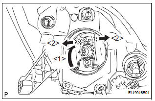
- Install the discharge headlight bulb with the set spring as shown in the illustration.

- Turn in the direction indicated by the arrow and install the socket.

- Turn in the direction indicated by the arrow and install the headlight socket cover.
6. INSTALL NO. 1 HEADLIGHT BULB (HALOGEN HEADLIGHT)

- Turn in the direction indicated by the arrow and install the No.1 headlight bulb.
 Adjustment
1. VEHICLE PREPARATION FOR HEADLIGHT AIMING
ADJUSTMENT
Prepare the vehicle:
Ensure there is no damage or deformation to the
body around the headlights.
Fill the fuel t ...
 Installation
1. INSTALL HEADLIGHT ASSEMBLY
Connect the connectors.
Install the headlight assembly with the bolt and 3
screws.
2. INSTALL FRONT BUMPER ASSEMBLY
3. CONNECT CABLE TO NEGATI ...
Other materials:
Inspection
1. INSPECT FRONT SPEED SENSOR
(a) Make sure that there is no looseness at the
connector lock part and connecting part of the
connector.
(b) Disconnect the speed sensor connector.
(c) Measure the resistance between terminals 1 and 2
of the speed sensor connector.
OK:
Resistance:
0.92 ...
System description
1. BRIEF DESCRIPTION
The CAN (Controller Area Network) is a serial data
communication system for real time application. It is
a vehicle multiplex communication system which
has a high communication speed (500 kbps) and
the ability to detect malfunctions.
By pairing the CANH and CANL bu ...
TC and CG Terminal Circuit
DESCRIPTION
DTC output mode is set by connecting terminals 13 (TC) and 4 (CG) of the
DLC3. The DTCs are indicated
by blinks of the tire pressure warning light.
WIRING DIAGRAM
HINT:
When each warning light blinks continuously, a ground short in the wiring of
terminal TC of the DLC3 or an ...