Toyota Sienna Service Manual: Removal
1. REMOVE FRONT WHEELS
2. REMOVE FRONT STABILIZER LINK ASSEMBLY LH
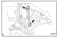
(a) Remove the 2 nuts and front stabilizer link assembly LH.
HINT: If the ball joint turns together with the nut, use a hexagon (6 mm) wrench to hold the stud.
3. REMOVE FRONT STABILIZER LINK ASSEMBLY RH
HINT: Remove the RH side by the same procedures as the LH side.
4. REMOVE FRONT STABILIZER BRACKET NO.1 LH

(a) Remove the 2 bolts and the front stabilizer bracket No.1 LH.
5. REMOVE FRONT STABILIZER BRACKET NO.1 RH
HINT: Remove the RH side by the same procedures as the LH side.
6. SEPARATE TIE ROD ASSEMBLY LH
HINT: (See page AH-4) SST 09628-62011
7. SEPARATE TIE ROD ASSEMBLY RH
SST 09628-62011
HINT: Separate the RH side by the same procedures as the LH side.
8. DISCONNECT PRESSURE FEED TUBE ASSEMBLY
HINT: (See page PS-21) SST 09023-12701
9. SEPARATE STEERING INTERMEDIATE SHAFT ASSEMBLY
HINT: (See page PS-21)
10. REMOVE RACK & PINION POWER STEERING GEAR ASSEMBLY
HINT: (See page PS-21)
11. REMOVE FRONT STABILIZER BAR BUSH NO.1
12. REMOVE STABILIZER BAR FRONT
 Front stabilizer bar (for 2wd)
COMPONENTS
...
 Inspection
1. INSPECT FRONT STABILIZER LINK ASSEMBLY LH
(a) As shown in the illustration, flip the ball joint stud
back and forth 5 times, before installing the nut.
(b) Using a torque wrench, turn the ...
Other materials:
A/C ECU Communication Stop
DTC B1262 A/C ECU Communication Stop
DESCRIPTION
DTC B1262 is output when communication between the A/C amplifier and the
multiplex network gateway
ECU stops for more than 10 seconds.
DTC No.
DTC Detection Condition
Trouble Area
B1262
A/C ECU communicat ...
Mass air flow meter
COMPONENTS
ON-VEHICLE INSPECTION
1. INSPECT MASS AIR FLOW METER
NOTICE:
Perform the mass air flow (MAF) meter inspection
by following the procedures below.
Only replace the MAF meter when the MAF value
in the DATA LIST (with the engine stopped) are
not within th ...
U151e automatic transaxle
SST
RECOMMENDED TOOLS
EQUIPMENT
LUBRICANT
SSM
...