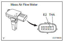
Toyota Sienna Service Manual: Mass air flow meter
COMPONENTS

ON-VEHICLE INSPECTION
1. INSPECT MASS AIR FLOW METER

NOTICE:
|
(a) Read the values using the intelligent tester (MAF).
NOTICE:
|
(1) Turn the ignition switch to the ON position (do not start the engine).
(2) Turn the tester on.
(3) Select the following menu items: DIAGNOSIS / ENHANCED OBD II / DATA LIST / PRIMARY / PRIMARY / MAF.
(4) Wait 30 seconds, and read the values on the intelligent tester.
Standard condition: Less than 0.70 g/s
- If the result is not as specified, replace the MAF meter.
- If the result is within the specified range, inspect the cause of the extremely rich or lean air fuel ratio.
REMOVAL
1. REMOVE MASS AIR FLOW METER

(a) Disconnect the mass air flow meter connector.
(b) Remove the 2 screws and mass air flow meter.
INSPECTION
1. INSPECT MASS AIR FLOW METER
(a) Visually check for any foreign matter on the platinum hot wire (heater) of the mass air flow meter.
OK: There is no foreign matter.
If the result is not as specified, replace the mass air flow meter.
(b) Measure the resistance according to the value(s) in the table below.
Standard resistance

INSTALLATION
1. REMOVE MASS AIR FLOW METER

(a) Install the mass air flow meter with the 2 screws.
(b) Connect the mass air flow meter connector.
 Accelerator pedal rod
COMPONENTS
ON-VEHICLE INSPECTION
1. CHECK ACCELERATOR PEDAL ROD
(a) Check the voltage.
(1) Connect the intelligent tester to the DLC3.
(2) Turn the ignition switch to the ON position.
...
 Vvt sensor
COMPONENTS
ON-VEHICLE INSPECTION
1. CHECK VVT SENSOR OUTPUT VOLTAGE
(a) Turn the ignition switch to the ON position.
(b) Check the voltage between the specified terminal
and body grou ...
Other materials:
Open in Curtain Shield Squib LH Circuit
DTC B1166/88 Open in Curtain Shield Squib LH Circuit
DESCRIPTION
The curtain shield squib LH circuit consists of the center airbag sensor
assembly and the curtain shield
airbag assembly LH.
The circuit instructs the SRS to deploy when deployment conditions are met.
DTC B1166/88 is recorde ...
Rear Room Temperature Sensor Circuit
DESCRIPTION
This sensor detects the rear cabin temperature that is used as the basis for
temperature control and
sends a signal to the A/C amplifier.
WIRING DIAGRAM
INSPECTION PROCEDURE
1 READ VALUE OF INTELLIGENT TESTER
(a) Connect the intelligent tester to the DLC3.
(b) Turn the ign ...
Reassembly
1. INSTALL FRONT DOOR WIRE LH
Install the wire with the 2 bolts.
Torque: Reference
8.0 N*m (82 kgf*cm, 71 in.*lbf)
NOTICE:
In order to prevent water leakage, be sure that
the lip of the rubber grommet does not turn up
or is not deformed when installing the wire.
Connect the wir ...