Toyota Sienna Service Manual: Removal
1. DRAIN POWER STEERING FLUID
2. REMOVE FRONT WHEEL RH
3. REMOVE FRONT FENDER APRON SEAL RH (See page EM-26)
4. REMOVE FAN AND GENERATOR V BELT (See page EM-6)
5. DISCONNECT NO. 1 FLUID RESERVOIR TO PUMP HOSE

(a) Slide the clip and disconnect the No. 1 fluid reservoir to pump hose from the vane pump assembly.
6. DISCONNECT PRESSURE FEED TUBE ASSEMBLY
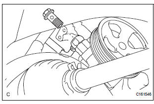
(a) Remove the union bolt and disconnect the pressure feed tube assembly from the vane pump assembly.
(b) Remove the gasket from the pressure feed tube assembly.
7. DISCONNECT POWER STEERING FLUID PRESSURE SWITCH CONNECTOR

(a) Disconnect the power steering fluid pressure switch connector.
8. REMOVE VANE PUMP ASSEMBLY
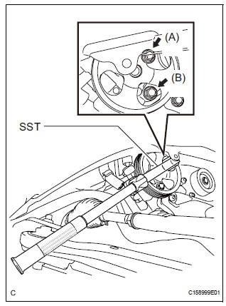
(a) Using SST, loosen bolt (A) and remove bolt (B), and then remove the vane pump assembly.
SST 09249-63010
(b) Remove the bolt from the vane pump assembly.
 Vane pump
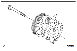
COMPONENTS
...
 Disassembly
1. HOLD VANE PUMP ASSEMBLY
(a) Using SST, hold the vane pump assembly in a vise.
SST 09630-00014 (09631-00132)
2. REMOVE POWER STEERING SUCTION PORT UNION
(a) Remove the bolt and the pow ...
Other materials:
Data list / active test
1. DATA LIST
HINT:
Using the intelligent tester to read the Data List allows
the values or states of switches, sensors, actuators and
other items to be read without removing any parts. This
non-intrusive inspection can be very useful because
intermittent conditions or signals may be discovered ...
Light Control Switch Circuit
DESCRIPTION
This circuit detects the state of the headlight dimmer switch.
WIRING DIAGRAM
INSPECTION PROCEDURE
1 READ VALUE OF INTELLIGENT TESTER
Connect the intelligent tester to DLC3.
Turn the ignition switch ON and push the intelligent
tester main switch ON.
Select t ...
Disassembly
1. REMOVE FUEL TANK TO FILLER PIPE HOSE (See
page FU-43)
2. REMOVE FUEL TANK MAIN TUBE SUB-ASSEMBLY
(a) Remove the tube joint clip, and pull out the fuel main
tube.
NOTICE:
Check if there is any dirt or mud around the
connector before this operation and remove
the dirt as ...