Toyota Sienna Service Manual: Removal
1. REMOVE V-BANK COVER SUB-ASSEMBLY (See page EM-28) 2. REMOVE NO. 1 ENGINE UNDER COVER (See page EM-26) 3. DRAIN ENGINE COOLANT (See page CO-6) 4. REMOVE NO. 2 AIR CLEANER INLET (See page EM- 28) 5. REMOVE BATTERY (See page EM-26) 6. REMOVE FRONT BUMPER ASSEMBLY (See page ET-3) 7. REMOVE FRONT BUMPER ENERGY ABSORBER 8. REMOVE NO. 1 AIR CLEANER INLET (See page EM- 28) 9. DISCONNECT RADIATOR RESERVE TANK HOSE OR PIPE

(a) Disconnect the radiator reserve tank hose or pipe from the radiator.
10. DISCONNECT NO. 1 RADIATOR HOSE

(a) Disconnect both connections of the No. 1 radiator hose from the radiator.
11. DISCONNECT NO. 2 RADIATOR HOSE
(a) Disconnect the No. 2 radiator hose from the radiator.
12. REMOVE HOOD LOCK RELEASE LEVER PROTECTOR

(a) Disengage the 4 claws and remove the hood lock release lever protector.

(b) Remove the 3 bolts.

(c) Disconnect the cable and remove the hood lock assembly.
14. REMOVE HOOD LOCK SUPPORT SUB-ASSEMBLY

(a) Disconnect the ambient temperature sensor connector.

(b) Detach the clamp.
(c) Disconnect the low pitched horn and high pitched horn connectors.

(d) Remove the 2 bolts and hood lock support subassembly.
15. DISCONNECT COOLING FAN ECU CONNECTOR

(a) Disconnect the cooling fan ECU connector.
(b) Detach the clamp.
16. REMOVE RADIATOR UPPER SUPPORT SUBASSEMBLY

(a) Remove the 4 bolts and radiator upper support subassembly.
17. DISCONNECT NO. 2 OIL COOLER OUTLET TUBE SUB-ASSEMBLY
(a) Disconnect the No. 1 oil cooler inlet and No. 1 oil cooler outlet hoses from the No. 2 oil cooler outlet tube sub-assembly.

(b) Disconnect the No. 1 transmission oil cooler hoses from the radiator.
(c) Remove the 2 bolts and No. 2 oil cooler outlet tube sub-assembly.
18. REMOVE HEADLIGHT ASSEMBLY RH
(a) Use the same procedures for the RH side and LH side
HINT: See page LI-69
19. REMOVE RADIATOR SIDE DEFLECTOR RH

(a) Disengage the 3 claws and remove the radiator side deflector RH.
20. REMOVE HEADLIGHT BRACKET RH

(a) Remove the 3 nuts and headlight bracket RH.
21. REMOVE PRESSURE FEED TUBE ASSEMBLY

(a) Remove the 2 bolts.
22. REMOVE RADIATOR SUPPORT CUSHION
(a) Remove the 2 radiator support cushions from the No. 1 radiator support.
23. REMOVE NO.1 RADIATOR SUPPORT

(a) Detach the clamp.

(b) Remove the 6 bolts and No. 1 radiator support.
24. REMOVE RADIATOR ASSEMBLY WITH FAN SHROUD AND FAN MOTOR

(a) Remove the 2 bolts and separate the condenser assembly from the radiator assembly with fan shroud and fan motor.

(b) Remove the radiator assembly with fan shroud and fan motor from the body.
25. REMOVE FAN SHROUD WITH FAN MOTOR
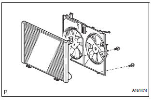
(a) Remove the 2 bolts and fan shroud with fan motor from the radiator.
26. REMOVE RADIATOR SUPPORT LOWER

(a) Remove the 2 radiator support lowers from the radiator assembly.
27. REMOVE NO. 2 RADIATOR SUPPORT

(a) Remove the 2 bolts and No. 2 radiator support from the radiator.
28. DISCONNECT INLET SUB-ASSEMBLY

(a) Disconnect the inlet hose from the radiator.
(b) Remove the bolt and inlet sub-assembly from the radiator.
 On-vehicle cleaning
1. INSPECT RADIATOR ASSEMBLY
(a) Check that the radiator and condenser are not
blocked with leaves, dirt, or insects. Clean the hose
connections.
If the fins are blocked, wash them with water or ...
 Disassembly
1. REMOVE RADIATOR WATER INLET
(a) Remove the 2 bolts and radiator water inlet.
2. REMOVE DRAIN PLUG
(a) Remove the drain plug and air drain plug.
(b) Remove the 2 O-rings.
3. REMOVE LOWER ...
Other materials:
Check mode procedure
HINT:
Check mode has a higher sensitivity to malfunctions and can
detect malfunction that normal mode cannot detect. Check
mode can also detect all the malfunctions that normal mode
can detect. In check mode, DTCs are detected with 1-trip
detection logic.
Dtc check (check mode)
HINT:
I ...
Television Display Assembly Communication Error
INSPECTION PROCEDURE
1 IDENTIFY THE COMPONENT SHOWN BY THE SUB-CODE
Enter the diagnostic mode.
Press the "LAN Mon" switch to change to "LAN Monitor"
mode.
Identify the component shown by the sub-code.
HINT:
"110 (multi-display)" i ...
Microphone Circuit between Microphone and Radio and Navigation
Assembly
DESCRIPTION
This circuit sends a microphone signal from the microphone to the radio and
navigation assembly.
It also supplies power from the radio and navigation assembly to the microphone.
WIRING DIAGRAM
INSPECTION PROCEDURE
1 INSPECT RADIO AND NAVIGATION ASSEMBLY
Measure the v ...