Toyota Sienna Service Manual: Seat Position Airbag Sensor Circuit Malfunction
DTC B1153/25 Seat Position Airbag Sensor Circuit Malfunction
DESCRIPTION
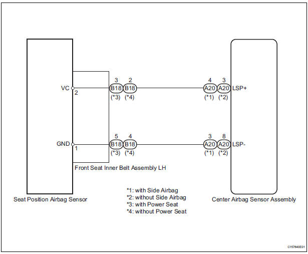
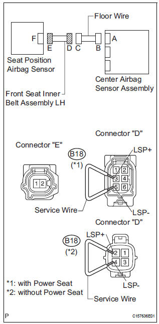
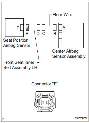
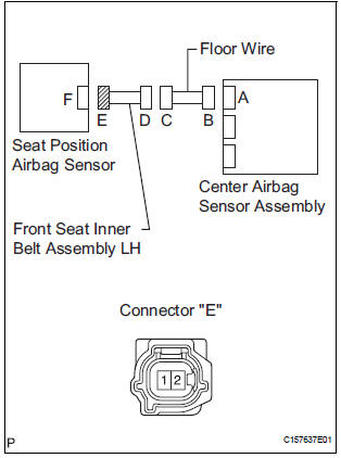
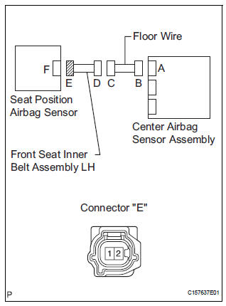
The seat position airbag sensor circuit consists of the center airbag sensor assembly and the seat position airbag sensor.
DTC B1153/25 is recorded when a malfunction is detected in the seat position airbag sensor circuit.
|
DTC No. |
DTC Detecting Condition |
Trouble Area |
|
B1153/25 |
|
|
WIRING DIAGRAM
INSPECTION PROCEDURE
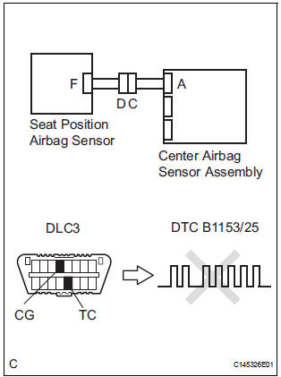
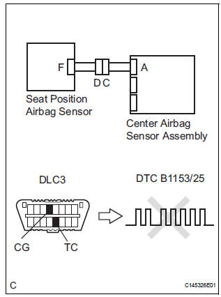
1 CHECK DTC
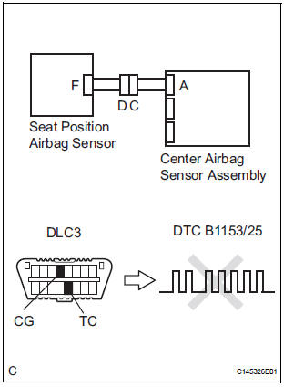
- Turn the ignition switch to the ON position, and wait for at least 60 seconds.
- Clear the DTCs stored in memory (5).
- Turn the ignition switch to the LOCK position.
- Turn the ignition switch to the ON position, and wait for at least 60 seconds.
- Check the DTCs (5).
OK: DTC B1153/25 is not output. HINT: Codes other than code B1153/25 may be output at this time, but they are not related to this check.
 Go to step 2

USE SIMULATION METHOD TO CHECK
2 CHECK CONNECTION OF CONNECTORS
- Turn the ignition switch to the LOCK position.
- Disconnect the negative (-) terminal cable from the battery, and wait for at least 90 seconds.
- Check that the connectors are properly connected to the center airbag sensor assembly, the seat position airbag sensor and front seat inner belt assembly LH.
OK: The connectors are connected.
 CONNECT CONNECTORS

3 CHECK CONNECTORS
- Disconnect the connectors from the center airbag sensor assembly, the seat position airbag sensor and front seat inner belt assembly LH.
- Check that the connectors are not damaged
OK: The connectors are not deformed or damaged.
 REPAIR OR REPLACE WIRE
HARNESS
REPAIR OR REPLACE WIRE
HARNESS

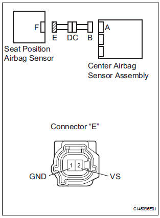
4 CHECK SEAT POSITION AIRBAG SENSOR CIRCUIT (OPEN)
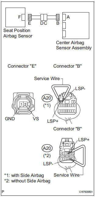
- Connect the connectors that link the front seat inner belt assembly LH and floor wire.
- with Side airbag:
Using a service wire, connect A20-4 (LSP+) and A20-3
(LSP-) of connector "B".
NOTICE: Do not forcibly insert a service wire into the terminals of the connector when connecting.
- without Side airbag:
Using a service wire, connect A20-3 (LSP+) and A20-8
(LSP-) of connector "B".
NOTICE: Do not forcibly insert a service wire into the terminals of the connector when connecting.
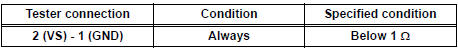
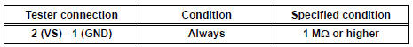
- Measure the resistance between the terminals of connector "E" according to the value(s) in the table below.
Standard resistance
 Go to step 11

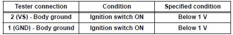
5 CHECK SEAT POSITION AIRBAG SENSOR CIRCUIT (SHORT TO B+)
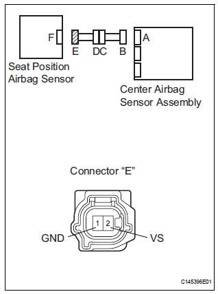
- Disconnect the service wire from connector "B".
- Connect the negative (-) terminal cable to the battery, and wait for at least 2 seconds.
- Turn the ignition switch to the ON position.
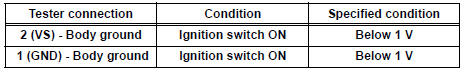
- Measure the voltage according to the value(s) in the table below.
Standard voltage
 Go to step 12

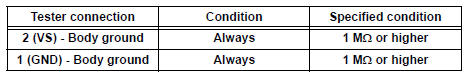
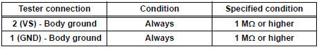
6 CHECK SEAT POSITION AIRBAG SENSOR CIRCUIT (SHORT TO GROUND)
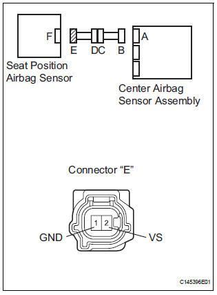
- Turn the ignition switch to the LOCK position.
- Disconnect the negative (-) terminal cable from the battery, and wait for at least 90 seconds.
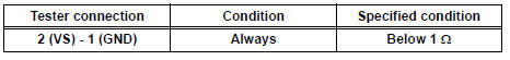
- Measure the resistance according to the value(s) in the table below.
Standard resistance
 Go to step 13

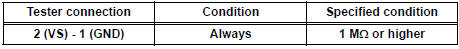
7 CHECK SEAT POSITION AIRBAG SENSOR CIRCUIT (SHORT)
- Measure the resistance according to the value(s) in the table below.
Standard resistance
 Go to step 14

8 CHECK SEAT POSITION AIRBAG SENSOR
- Connect the connectors to the seat position airbag sensor and the center airbag sensor assembly.
- Connect the negative (-) terminal cable to the battery, and wait for at least 2 seconds.
- Turn the ignition switch to the ON position, and wait for at least 60 seconds.
- Clear the DTCs stored in memory (5).
- Turn the ignition switch to the LOCK position.
- Turn the ignition switch to the ON position, and wait for at least 60 seconds.
- Check the DTCs (5).
OK: DTC B1153/25 is not output. HINT: Codes other than code B1153/25 may be output at this time, but they are not related to this check.
 Go to step 9

USE SIMULATION METHOD TO CHECK
9 REPLACE SEAT POSITION AIRBAG SENSOR
- Turn the ignition switch to the LOCK position.
- Disconnect the negative (-) terminal cable from the battery, and wait for at least 90 seconds.
- Replace the seat position airbag sensor.
HINT: Perform the inspection using parts from a normal vehicle if possible

10 CHECK CENTER AIRBAG SENSOR ASSEMBLY
- Connect the negative (-) terminal cable to the battery, and wait for at least 2 seconds.
- Turn the ignition switch to the ON position, and wait for at least 60 seconds.
- Clear the DTCs stored in memory (5).
- Turn the ignition switch to the LOCK position.
- Turn the ignition switch to the ON position, and wait for at least 60 seconds.
- Check the DTCs (5).
OK: DTC B1153/25 is not output. HINT: Codes other than code B1153/25 may be output at this time, but they are not related to this check.
 REPLACE CENTER AIRBAG SENSOR
ASSEMBLY
REPLACE CENTER AIRBAG SENSOR
ASSEMBLY

END
11 CHECK FRONT SEAT INNER BELT ASSEMBLY LH (OPEN)
- Disconnect the service wire from connector "B".
- Disconnect the floor wire connector from the front seat inner belt assembly LH.
- with Power seat:
Using a service wire, connect B18-3 (LSP+) and B18-5
(LSP-) of connector "D".
NOTICE: Do not forcibly insert a service wire into the terminals of the connector when connecting.
- without Power seat:
Using a service wire, connect B18-2 (LSP+) and B18-4
(LSP-) of connector "D".
NOTICE: Do not forcibly insert a service wire into the terminals of the connector when connecting.
- Measure the resistance according to the value(s) in the table below.
Standard resistance
 REPLACE FRONT SEAT INNER BELT
ASSEMBLY LH
REPLACE FRONT SEAT INNER BELT
ASSEMBLY LH

REPAIR OR REPLACE FLOOR WIRE
12 CHECK FRONT SEAT INNER BELT ASSEMBLY LH (SHORT TO B+)
- Turn the ignition switch to the LOCK position.
- Disconnect the negative (-) terminal cable from the battery, and wait for at least 90 seconds.
- Disconnect the floor wire connector from the front seat inner belt assembly LH.
- Connect the negative (-) terminal cable to the battery, and wait for least 2 seconds.
- Turn the ignition switch to the ON position.
- Measure the voltage according to the value(s) in the table below.
Standard voltage
 REPLACE FRONT SEAT INNER BELT
ASSEMBLY LH
REPLACE FRONT SEAT INNER BELT
ASSEMBLY LH

REPAIR OR REPLACE FLOOR WIRE
13 CHECK FRONT SEAT INNER BELT ASSEMBLY LH (SHORT TO GROUND)
- Disconnect the floor wire connector from the front seat inner belt assembly LH.
- Measure the resistance according to the value(s) in the table below.
Standard resistance
 REPLACE FRONT SEAT INNER BELT
ASSEMBLY LH
REPLACE FRONT SEAT INNER BELT
ASSEMBLY LH

REPAIR OR REPLACE FLOOR WIRE
14 CHECK FRONT SEAT INNER BELT ASSEMBLY LH (SHORT)
- Disconnect the floor wire connector from the front seat inner belt assembly LH.
- Measure the resistance according to the value(s) in the table below.
Standard resistance
 REPLACE FRONT SEAT INNER BELT
ASSEMBLY LH
REPLACE FRONT SEAT INNER BELT
ASSEMBLY LH

REPAIR OR REPLACE FLOOR WIRE
 Passenger Airbag ON/OFF Indicator Circuit
Malfunction
Passenger Airbag ON/OFF Indicator Circuit
Malfunction
DTC B1152/28 Passenger Airbag ON/OFF Indicator Circuit
Malfunction
DESCRIPTION
The passenger airbag ON/OFF indicator circuit consists of the center airbag
sensor assembly and
passenger airbag ON ...
 Rear Airbag Sensor RH Circuit Malfunction
DTC B1154/38 Rear Airbag Sensor RH Circuit Malfunction
DESCRIPTION
The rear airbag sensor RH circuit consists of the center airbag sensor
assembly and rear airbag sensor
RH.
If the center airb ...
Other materials:
Disassembly
1. REMOVE STEERING INTERMEDIATE SHAFT ASSEMBLY
(a) Align the matchmarks on the steering intermediate
shaft assembly and main shaft.
(b) Remove the bolt and steering intermediate shaft
assembly.
2. REMOVE KEY CYLINDER LIGHT ASSEMBLY (w/o
Engine Immobiliser System)
3. REMOVE TRANSPONDER K ...
Power back door system
PARTS LOCATION
...
Installation
1. INSTALL SEAT POSITION AIRBAG SENSOR
Check that the ignition switch is off.
Check that the negative battery (-) terminal is
disconnected.
CAUTION:
After disconnecting the negative battery
terminal, wait for at least 90 seconds before
starting the operation.
Usin ...